SC-F9200 Series Revision B
DISASSEMBLY & ASSEMBLY Disassembly and Assembly Procedure 141
SE Group Confidential (Related Staff Only)
Figure 3-74. Holding Up the Ink Path Holder Assy
7. Remove the four screws that secure the Ink Path Joint and remove it.
B) Silver M3x10 screw with washer: 4 pcs
8. Remove the Joint Rubbers two each from the two Ink Path Joints.
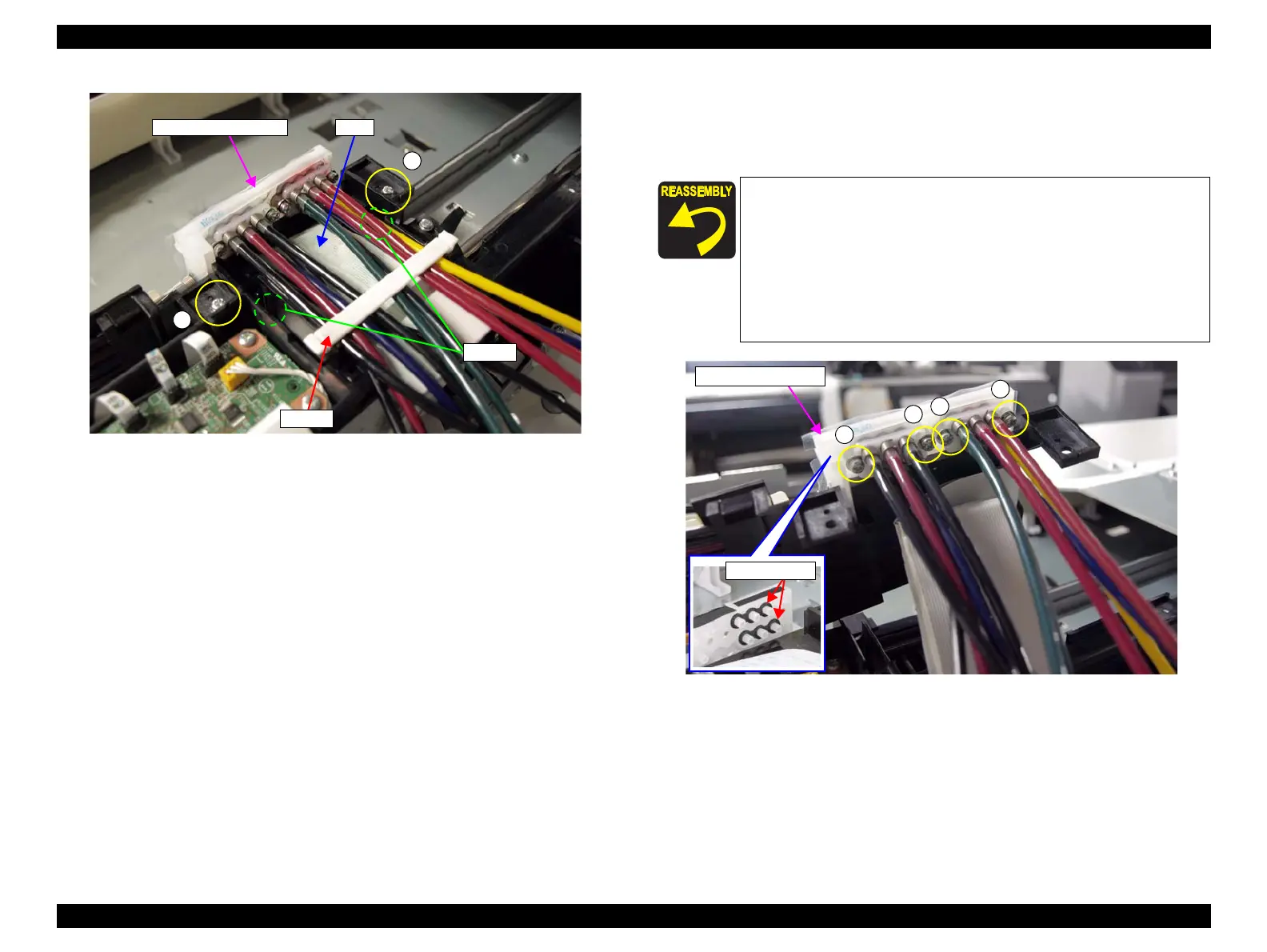
Figure 3-75. Removing the Ink Path Joint
A
A
Ink Path Holder Assy
FFC
Clamp
Hooks
Before attaching the Joint Rubbers, let them get wet with
cleaning liquid (CL14).
Secure the screws that secure the Ink Supply Tube with
tightening torque about 0.29 ± 0.05 Nm.
Confirm there are no foreign objects attached on the Joint
Rubbers.
If the Joint Rubbers are deformed, restore it to its original
shape manually.

 Loading...


