SC-F9200 Series Revision B
DISASSEMBLY & ASSEMBLY Disassembly and Assembly Procedure 171
SE Group Confidential (Related Staff Only)
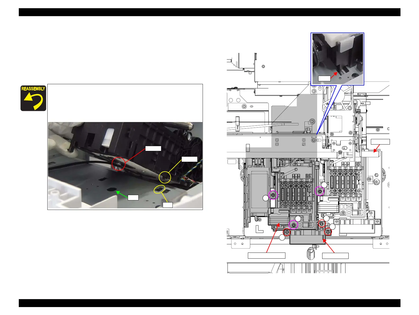
9. Remove the three screws, and remove the CR Stopper.
C)Silver M3x8 screw: 3 pcs
10. Remove the three screws that secure the Pump Cap Unit 1.
D)Silver M3x8 S-tite screw with built-in washer: 3 pcs
11. Pull the Pump Cap Unit 1 frontward to disengage the hook, and remove the Pump
Cap Unit 1 avoiding contact with the CR shaft or any other parts.
Figure 3-112. Removing the Pump Cap Unit 1
12. Pull out the Pump Cap Unit 1.
Install the Pump Cap Unit 1 while aligning its screw head with
the hole on the frame. If they do not match, the current
attachment position is wrong.
Align the hook on the Pump Cap Unit 1 with the hole on the
frame shown in the figure below.

 Loading...


