SC-F9200 Series Revision B
DISASSEMBLY & ASSEMBLY Disassembly and Assembly Procedure 245
SE Group Confidential (Related Staff Only)
3.4.9.2 Reel Unit
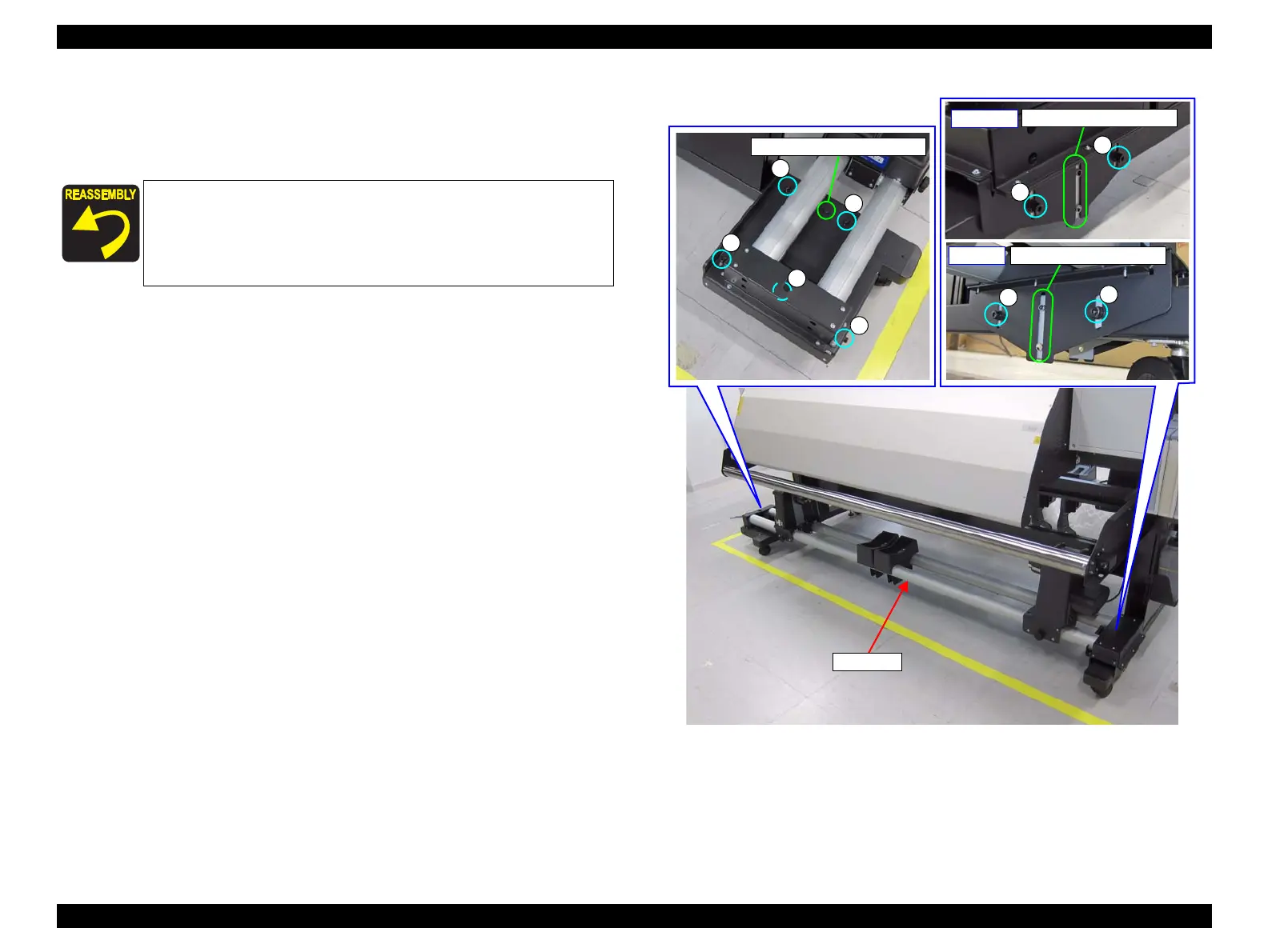
1. Remove the nine screws, and remove the Reel Unit.
A) Special screw: 9 pcs
Figure 3-200. Removing the Reel Unit (SC-F7100 Series)
When installing the Reel Unit, confirm the following.
On the left side of the Reel Unit, insert the dowel of the frame
into the positioning hole on the Reel Unit.
On the right side of the Reel Unit, insert the dowels of the frame
into the positioning grooves of the Reel Unit.
A
A
A
A
A
Positioning hole and dowel
A
A
Dowel and positioning groove
- Inside -
A
A
Dowel and positioning groove
- Outside -

 Loading...


