EPSON Stylus CX3100/3200 Revision A
Disassembly and Assembly Disassembly Process 39
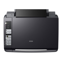
5. Using tweezers or the like, disengage the upper and lower hooks on the Harness
Fastening Plate which retain the Harness Fastening Plate to the Shield Cover for
the Main Board.
Figure 4-4. Harness Fastening Plate
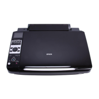
6. Remove the Ferrite Core from the Shield Cover for the Main Board.
Figure 4-5. Ferrite Core
7. Disconnect the four lines of harness of the Scanner Unit from the Main Board.
CCD harness: CN1
HP detector harness: CN2
Panel harness: CN6
Motor harness: CN7
8. Remove the Ferrite Cores from the CCD harness and Panel harness.
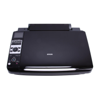
9. Remove the two (right and left) screws (CBP-Tite 3x10 F/Ni) securing the Scanner
Unit to the Middle Housing.
NOTE: Screw tightening torque: 0.5-0.7 Nm
Figure 4-6. Screws securing the Scanner Unit
10. Remove the Scanner Unit upward.
Harness Fastening Plate
Ferrite Core
C A U T I O N
When removing the Scanner Unit, take care not to damage the
harness.
CBP-Tite 3x10 F/Ni
 Loading...