EPSON Stylus CX3100/3200 Revision A
Disassembly and Assembly Scanner Unit Disassembly 43
4.3.4 CCD Module Removal
1. Remove the scanner unit. (Refer to “Scanner Unit Removal” on page 38)
2. Remove the hinge. (See “Hinge Removal” on page 40)
3. Remove the upper housing. (See “Upper Housing Removal” on page 41)
4. Disconnect the FFC from the lower housing.
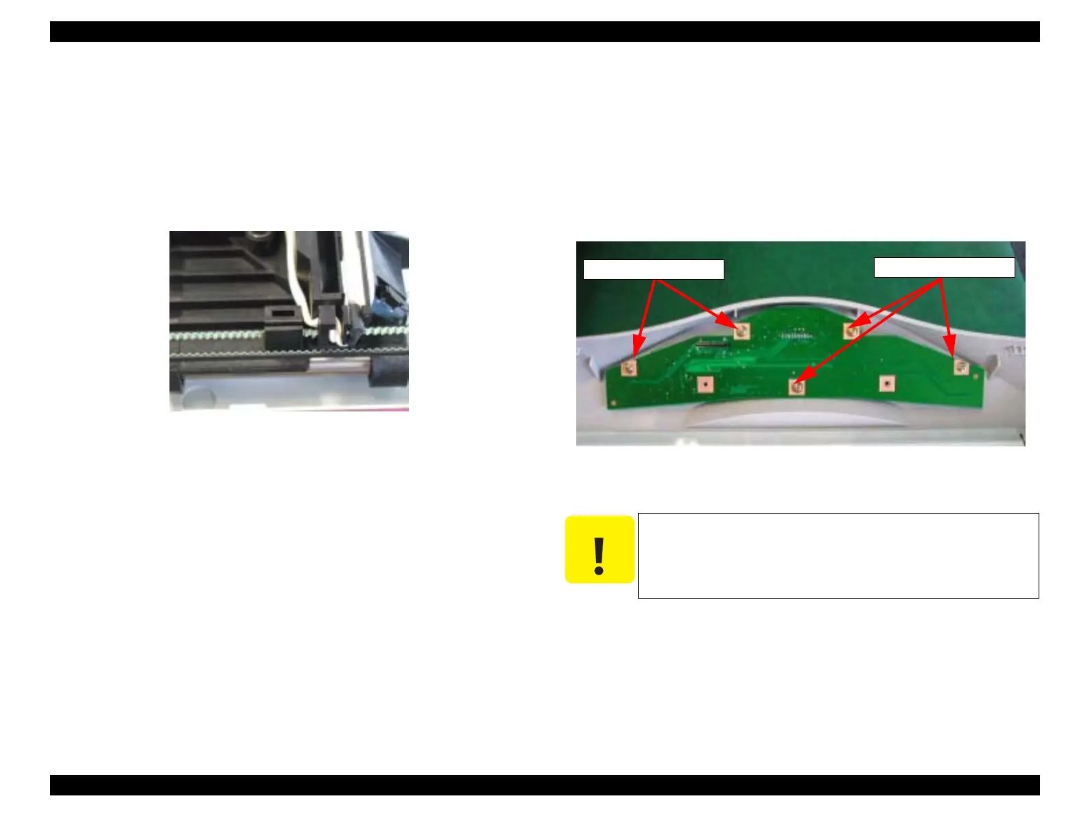
5. Disengage the timing belt from the retaining portion of the CCD module.
Figure 4-15. Timing Belt Retaining Portion
6. Remove the guide shaft from the lower housing.
7. Remove the guide shaft from the CCD module.
4.3.5 Panel Circuit Board Removal
1. Remove the scanner unit. (Refer to “Scanner Unit Removal” on page 38)
2. Remove the hinge. (See “Hinge Removal” on page 40)
3. Remove the upper housing. (See “Upper Housing Removal” on page 41)
4. Remove the five screws (CCP-Tite 3x6 F/Zb) securing the panel circuit board.
NOTE: Screw tightening torque: TBD
Figure 4-16. Screws securing the Panel Circuit Board
C A U T I O N
When installing the panel circuit board, take care that no dust
enters between the LCD panel and the transparent cover.
Do not touch the switch contacts on the panel circuit board
with bare hand; otherwise, contact error can occur.
CCP-Tite 3x8F/Zn
CCP-Tite 3x8F/Zn
 Loading...