EPSON Stylus CX3100/3200 Revision A
Disassembly and Assembly Disassembly of Printer 54
4.4.8 Main Board Removal
1. Remove the Middle Housing. (See “Middle Housing Removal” on page 44.)
2. Remove the ASF Unit. (See “ASF Unit Removal” on page 48)
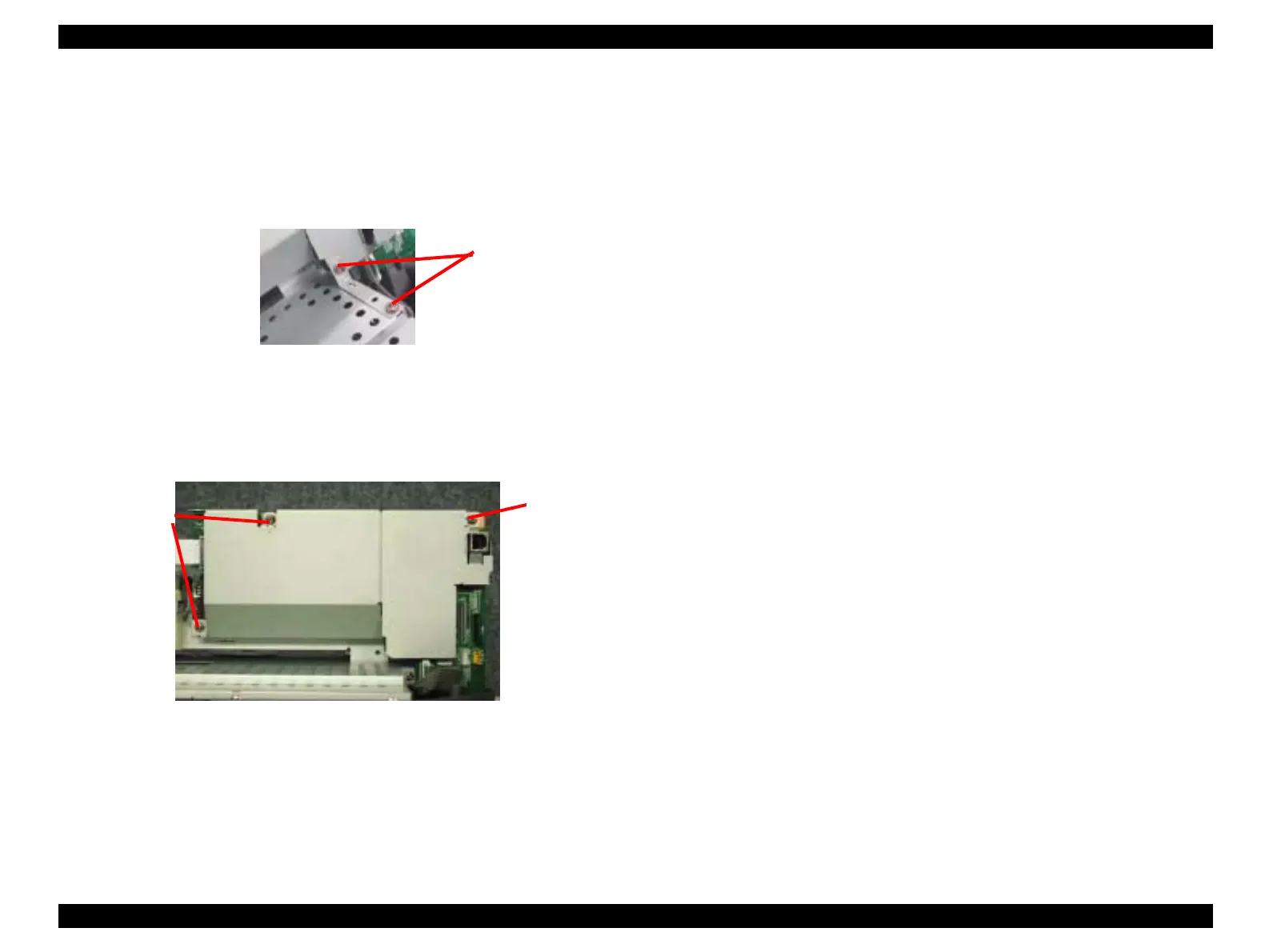
3. Remove the two screws (C.B.S. 3x6 F/Zn) securing the M/B Grounding Plate to the
Shield Cover and remove the M/B Grounding Plate.
Figure 4-36. M/B Grounding Plate
NOTE: Screw tightening torque;C.B.S. 3x6, F/Zn (2 pcs.): 0.5-0.7Nm
4. Remove the three screws (C.B.S. 3x6 F/Zn) securing the Main Board and Shield Cover
to the Printer Mechanism.
Figure 4-37. Removing the Main Board
NOTE: Screw tightening torque;C.B.S. 3x6, F/Zn (3 pcs.): 0.5-0.7Nm
5. Disconnect the following lead wires from the respective connectors on the Main
Board.
Power Supply Board: CN5
HP/PE sensor lead wires: CN4
Head FFC: CN8 and 9
PF Motor lead wires: CN13
PF Motor lead wires: CN14
C.B.S. 3x6 F/Zn
C.B.S. 3x6
C.B.S. 3x6
 Loading...