EPSON Stylus CX3100/3200 Revision A
Disassembly and Assembly Disassembly of Printer 55
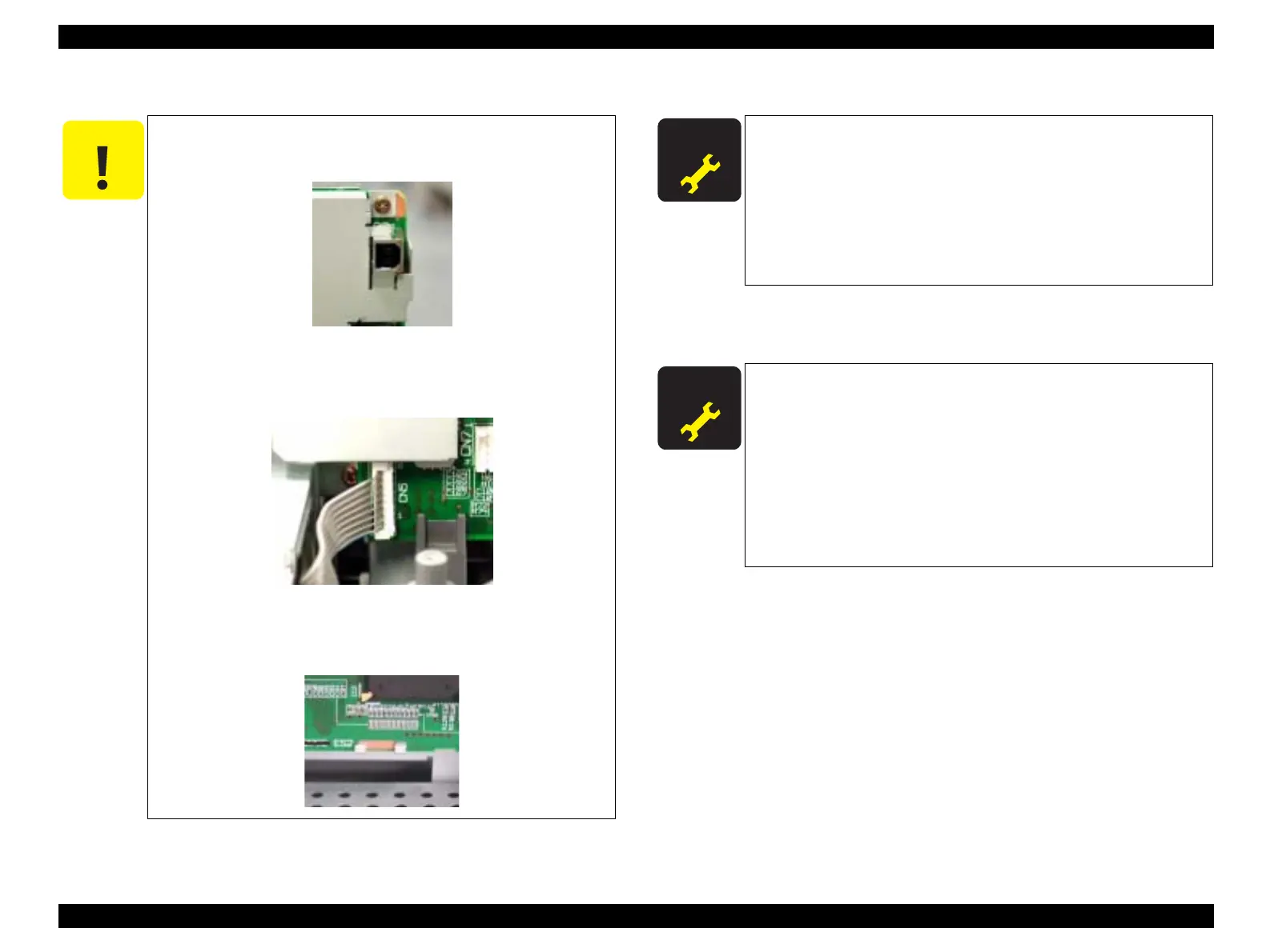
C A U T I O N
Install the Shield Cover on the Main Board so that the USB
connector is held in the Shield Cover. (See below)
Connect the power supply cable on the secondary side to the
Main Board so that the blue-band cable end is positioned at pin
1 as shown below.
When installing the Main Board in the Printer Mechanism
Unit, engage the Main Board with the hooks on the Mechanism
Unit as shown below.
A D J U S T M E N T
R E Q U I R E D
Once you have replaced the Main Board with a new one, make the
following adjustments:
Destination Setting (EEPROM Initialization) (See p.61)
Head ID Input (See p.62)
Bi-D Adjustment (See p.63)
USB ID Input (See p.65)
Top Margin Adjustment (See p.66)
First Dot Position Adjustment (See p.67)
A D J U S T M E N T
R E Q U I R E D
When you have removed once and installed the Main Board, make
the following adjustments:
Bi-D Adjustment (See p.63)
There may be cases where the contents of EEPROM on the Main
Board can be read, for example, when only the motor driver has
broken down. In such cases, to shorten repair time, you can back
up only the adjusted values by executing the following operation
and download the adjusted values onto the newly installed Main
Board.
EEPROM Data Backup (See p.70)
 Loading...