EPSON Stylus CX3100/3200 Revision A
Disassembly and Assembly Disassembly of Printer 44
4.4 Disassembly of Printer
This section describes the disassembly procedure for the printer of Stylus CX3100/
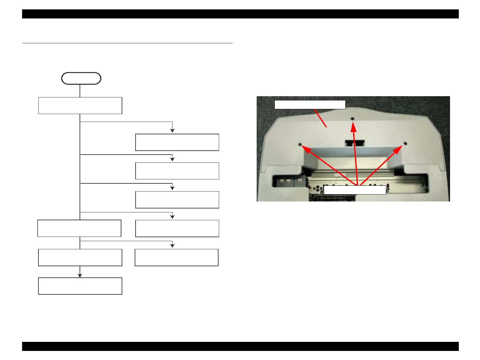
3200. Figure 4-17 below shows the flowchart for disassembly procedure.
Figure 4-17. Flowchart (3)
4.4.1 Middle Housing Removal
1. Remove the scanner unit. (Refer to “Scanner Unit Removal” on page 38)
2. Remove the three screws (CBP-Tite 3x10 F/Ni) securing the Front Housing to the
Middle Housing.
NOTE: Screw tightening torque: 0.5-0.7 Nm
Figure 4-18. Screws securing the Front Housing
3. Remove the Front Housing.
4. Remove the four screws (CBP 3x10 F/Zn) securing the Middle Housing to the Porous
Pad Tray.
START
“Middle Housing Removal”
on page 44
“Print Head Removal”
on page 46
“Holder Shaft Unit Removal”
on page 52
“Main Board Removal”
on page 54
“CR Motor Removal”
on page 50
“Front Frame Unit Removal”
on page 53
“ASF Unit Removal”
on page 48
“Waste Ink Pad Removal”
on page 49
“Power Unit Removal”
on page 56
Front Housing
CBP-Tite 3x10
 Loading...