EPSON Stylus CX3100/3200 Revision A
Disassembly and Assembly Disassembly Process 38
4.2 Disassembly Process
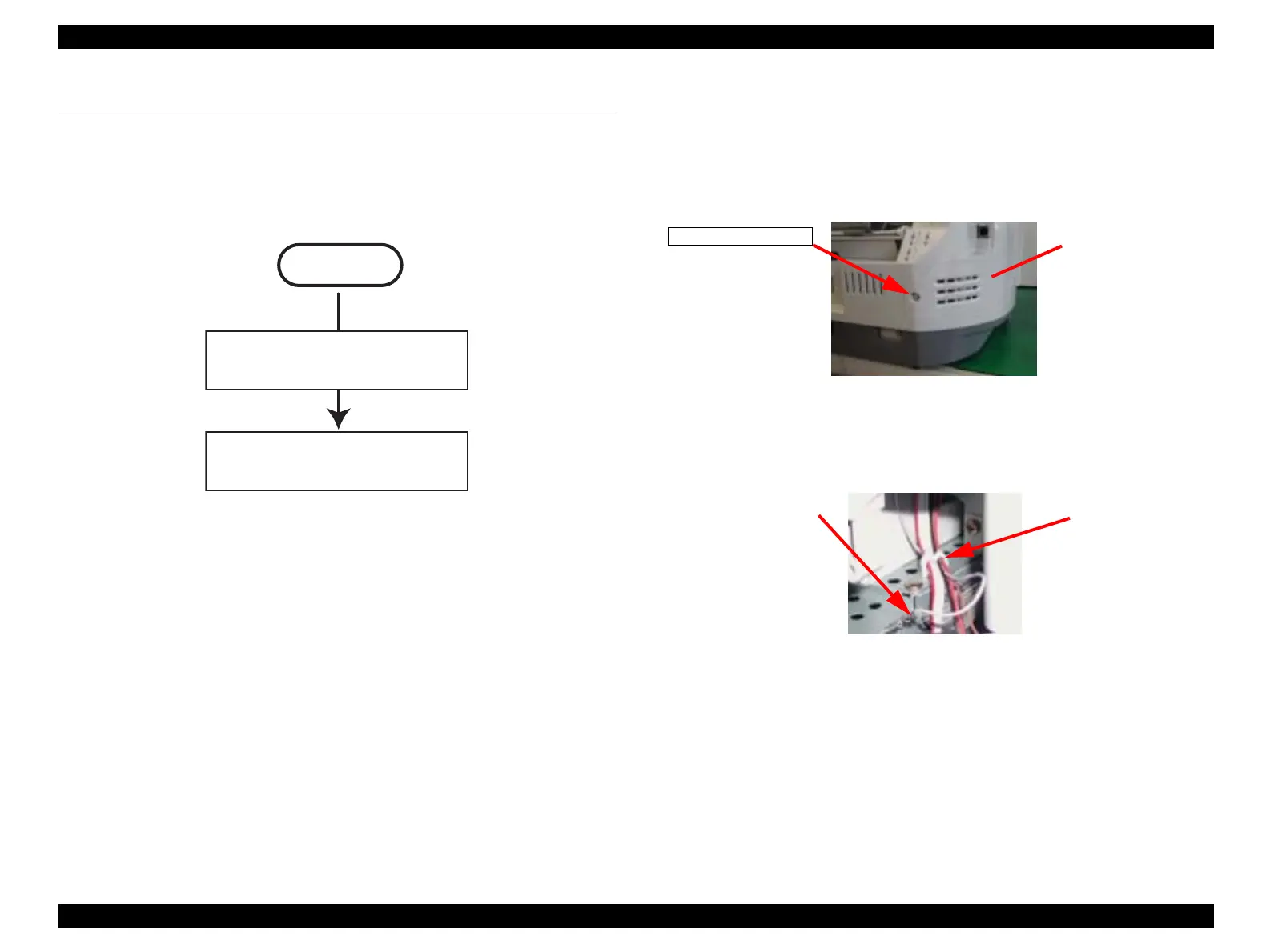
The flowchart below shows Disassembly Process
Figure 4-1. Flowchart (1)
4.2.1 Scanner Unit Removal
1. Remove the one screw (CBP-Tite 3x10 F/Zn) securing the FFC Cover to the Middle
Housing.
NOTE: Screw tightening torque: 0.5 -0.7 Nm
Figure 4-2. Screw securing the Connector Cover
2. Remove the FFC Cover.
3. Disconnect the Harness Grounding Plate from the terminals on the Power Supply Unit.
Figure 4-3. Harness Grounding Plate
4. Release the harness of the Scanner from the Mini Clamp on the Power Supply Unit.
START
“Scanner Unit Removal”
on page 38
“Disassembly of Printer”
on page 44
CBP-Tite 3x10
FFC Cover
Harness Grounding Plate
Mini Clamp
 Loading...