EPSON Stylus CX3100/3200 Revision A
Disassembly and Assembly Disassembly of Printer 51
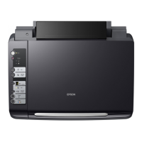
6. Release the motor lead wires from the fastening portion of the Holder Shaft Unit.
Figure 4-32. Releasing the Motor Lead Wires
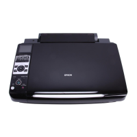
7. While holding the motor, remove the four hexagon nuts (M3) securing the motor to the
mechanism.
Figure 4-33. Removing the CR Motor
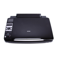
C A U T I O N
When installing the CR Motor, pay attention to the following
particulars:
Connect the motor lead wires to the connector (CN14) on the
Main Board.
Tighten the hexagon nuts in the numeric order shown below.
NOTE: Screw tightening torque: 0.5-0.7Nm
Check that the motor is secured properly.
A D J U S T M E N T
R E Q U I R E D
CR
Once the CR Motor has been removed or replaced, make
adjustments in the order specified below:
1. Bi-D Adjustment (See p.63)
2. First Dot Position Adjustment (See p.67)
1 4
2
3
 Loading...