WF-C20590 Installation Guide
Installing the Optional Units 39
26. After securing the Lock Lever, you may need to adjust the Bridge Unit casters.
The Bridge Unit is initially set at 3.5 mm lower than the printer height, but some
floors may be uneven so adjustments may be required. See Step 27 for instructions
on how to adjust the casters, then check the following cases below.
CASE 1: The casters on the right (printer side) do not touch the floor (start at
Step 32 and end with Step 41).
CASE 2: The casters on the right (printer side) touch the floor (start at Step 31,
then go to Step 32, and end with Step 41).
CASE 3: The casters on the right (printer side) touch the floor, and the magnets on
the ends of the EJ Cover are attached to the plate (no adjustments are needed, go to
Step 42).
HOW TO ADJUST THE CASTERS
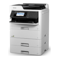
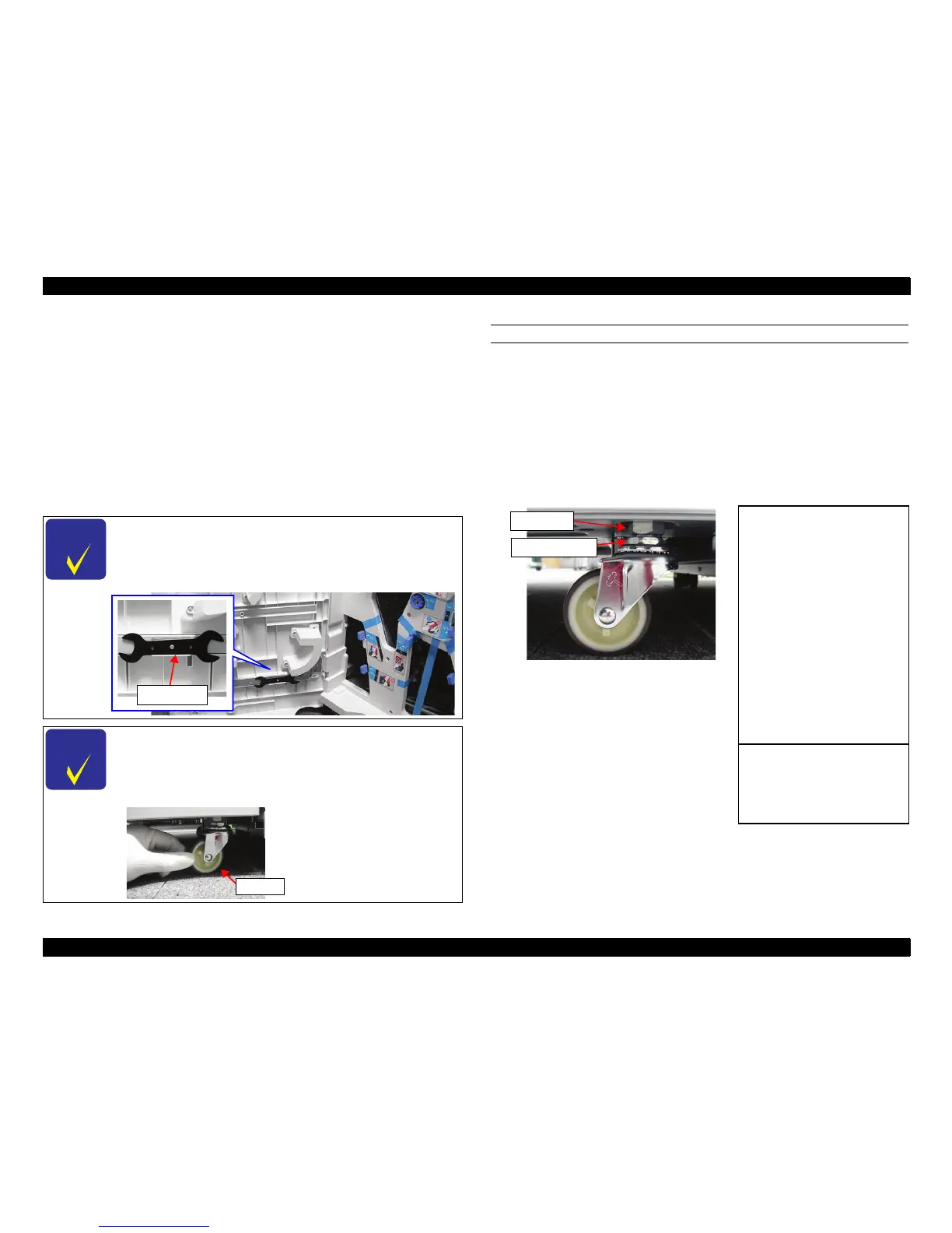
27. Loosen the Fixing Nut on one caster (turn clockwise to loosen, or
counterclockwise to tighten).
28. Adjust the height with the Adustment Nut. One full turn of the Adjustment Nut
raises or lowers the Bridge Unit by about 1.75 mm (see the table below for more
measurements).
Clockwise: The caster lowers (the Bridge Unit rises).
Counterclockwise: The caster rises (the Bridge Unit lowers).
29. Tighten the Fixing Nut after the adjustment is complete.
30. Adjust the remaining casters.
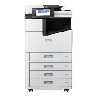
You can determine if the casters on the right (printer side)
touch the floor or not by rotating the caster.
If you can rotate the caster, it is not touching the floor.
If you cannot rotate the caster, it is touching the floor.
 Loading...