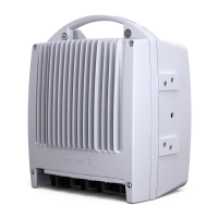
MINI-LINKEandEMicro
6.1.2 Communication Channels
MINI-LINK E
RAU
NCC
A M M , M K II
or
MINI-LINK C
AM M
EAC
SITE A SITE B SITE C
SAU
(M X U )
F ix e d lin e
AM M
AM M
HCC
RCC
MINI-LINK E
RAU
MINI-LINK E
RAU
SAU
(M X U )
HCC
MINI-LINK E
Micro
SITE D
AM M
MINI-LINK E
Micro
MINI-LINK E
Micro
2 M bit/s
to B T S
NCC
NCC
NCC
RCB
3566
Figure 67 C onnection of terminals through the communication channels
The Node Communication Channel (NCC) is used for distribution of operation
and maintenance data between units in one or two MINI-LINK E Access Module
Magazines (AMMs). NCC connection between units in one AMM is done
through the backplane, but for connection between two AMMs a connector on
the MMU front is used.
NCC is also used for distribution of operation and maintenance data between up
to three MINI-LINK E Micro radios on the same site. Connectors for MINI-LINK
E Micro are located inside the Radio Connection Box (RCB).
Alternatively, the EAC connector on the SAU can be used for interconnection
of AM Ms within a site. EAC must be used for interconnection of more than
two AMMs.
Data between indoor units and the Radio Unit (RAU) is distributed through the
Radio Com munication Channel (RCC). Over the hop, data between terminals
is distributed through the H op Communication Channel (HC C).
Data to other MINI-LINK E access modules on the same site or to other
MINI-LINK equipment on the site is distributed through the External Alarm
Channel (EAC) in the SAU. Operation and maintenance data to and from other
MINI-LINK clusters is distr ibuted through the Remote Alarm Channel (RAC)
through a fixed line (RS 232C or ITU-T G.703 64 kbit/s) in the SAU. The O&M
95
AE/LZT 110 2012 R8C 2002- 03-04

 Loading...