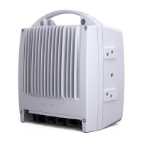
MINI-LINKEandEMicro
MUX
X
SMU
MMU2
MMU1
CPU
Tx On/Off
RAU A
RAU B
CPU
Tx On/Off
RMX
Traffic
T1
T2
X
X
2 Mbit/s
*
Traffic
*
MMU 34+2 only
CPU - Control & Supervision processor
RMX - Radio Frame Multiplexer
X - Traffic Router
T1 - Traffic channel 1
T2 - Traffic channel 2
MUX - Multiplexer
RMX
1+1
Switch
Logic
3534
Figure 45 1+1 protection switching for the transmitter
Receiver Switching
There are two types of receiver swit ching: hardware failure switching and hitless
switching due to fading. The switching functionality is physically implemented in
two different kinds of switch, the RMX switch and a hardware switch, see Figure
46 on page 62. Selection is based on alarm information from the receiver
section of the radio unit or the MMU, see Table 2 on page 60. However, hitless
switching is performed in the RMX switch. Selection can also be made manually
from the MMU front or from a PC. An alar m with high priority overrides an alar m
with lower priority. The radio unit with the lowest priority alarm receives the
signal. See Section 6.1.4.1 on page 97 for a description of the alarms.
59
AE/LZT 110 2012 R8C 2002- 03-04

 Loading...