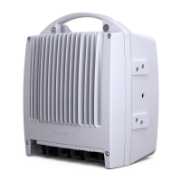
MINI-LINKEandEMicro
6.1.8 Performance Monitoring
Transmission performance according to ITU-T Rec G.826 is measured and
stored. In case of protected operation, the perform ance for the protected path
is measured and stored.
6.1.9 Received Signal Level Monitoring
The received signal level is measured for the monitoring of:
• Antenna alignment (measured with external voltmeter in radio unit)
•Pa
th acceptance to check that the actual RF input level equals the one
pr
edicted (measured with a PC or a local display)
• Alar m generation
• RF input monitoring (measured with a P C or a local display)
• Long time RF input level measurement to discover slow degradation in
system gain
6.1.10 Summary Alarm
The following summary alar m s (applicable for MINI-LINK E) are available at the
access module (SAU) as parallel relay outputs:
• A-alarm - indicates traffic disturbing faults which calls for immediate action
• B-alarm - risk of disturbed traffic
In the event of DC power supply failure, both summary A-alarm and summary
B-alarm will go active.
6.1.11 U ser Input/Output
The User Input ports (applicable for MINI-LINK E) can be used to connect
user’s alarms to the MINI-LINK Operation and M aintenance network. The
user’s alarms can for example be a fire alarm or a power supply alarm.
The User Output ports can be used for control of remote user’s functions. They
can also be used to connect summary alarms from the access module to the
users’ supervisor y system.
The SAU is required for the user input/output function. Eight User Input ports
and four selectable Input or Output ports are available.
108
AE/LZT 110 2012 R8C 2002-03-04

 Loading...