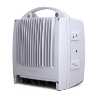
MINI-LINKEandEMicro
3.3.1 Block Diagram
Final
Amplifier
Transmitter
Transmit IF
Signal
Processing
Transmit IF
Signal,
350 MHz
Branching
Filter
DC/DC Converter
Command
& Control
Signal
Cable Interface
Control &
Supervision
Processor
Down
Converter
Low
Noise
Amplifier
Output
Level
Control
Antenna
RF Loop
FREQUENCY
CONTROL
Receive IF
Signal,
140 MHz
Receive IF
Signal
Processing
To
Alignment Port
TX OFF
Power
Detector
Receiver
FREQUENCY
CONTROL
Secondary
Voltages
Alarm
and
Control
Filter
Unit
RF Attenuator
(accessory)
Up
Converter
Branching
Filter
Filter
&
Amplifier
Receiver
Oscillator
Transmitter
Oscillator
Microwave Sub-unit
OUTPUT
LEVEL SET
MMU
3538
Figure 27 RAU1 7-E and 8-E block diagram
3.3.2 Microwave Sub-unit
The following functions are in
cluded in the microwave sub-unit:
• DC/DC Converter
• Cab le interface
• Control and supervision
• Transmit signal processing
• Receive signal processing
The microwave sub-unit consists of a microstrip board with an aluminum cover
that provides shielded compartments for the high-frequency circuits. The
control circuit board is fitted to the back of the microstrip board.
The microwave sub-unit is fully independent of transmission rates.
A microwave sub-unit covers several sub-bands. The sub-band is defined by
the microwave sub-unit together with the filter unit.
26
AE/LZT 110 2012 R8C 2002-03-04

 Loading...