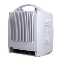
MINI-LINKEandEMicro
The f requency is synthesizer controlled. Each radio unit covers a sub-band
of the frequency band and has a fixed duplex distance ( difference between
transmitted and received frequency). The width of t he sub-band covered by a
specific version is different for different frequencies in accordance with the table
above. The values in brackets are gained by replacement of the filter unit.
Frequency Plans
The radio unit is available for different frequency channel arrangements
according to ITU-R and ETS I recommendations.
See f requency plans in MINI-LINK E and E Micro Product Catalog (AE/LZT
110 2011).
Frequency Tolerance
±10 ppm from nominal.
Channel Spacing for MINI-LINK E
• 3.5 MHz for 2x2 Mbit/s
• 7 MHz for 4x2 and 8 Mbit/s
• 14 MHz for 2x8 and 8x2 Mbit/s (13.75 MHz for 18 GHz)
• 28 MHz for 17x2 and 34+2 Mbit/s (27.5 MHz for 18 GHz)
Channel Spacing for MINI-LINK E Micro
• 3.5 MHz for 1x2 and 2x2 Mbit/s
8.1.1 Transmitter Performance
All radio units, except for RAU1 26-E and RAU1 38-E, have built-in variable
attenuators that can be adjusted from MINI-LINK Netman or MSM. RAU1 26-E
and RAU1 38-E have mechanically adjustable attenuators.
In addition to var i able attenuators, all RAU1 radios can have optional fixed RF
attenuators fitted inside the radio unit.
126
AE/LZT 110 2012 R8C 2002-03-04

 Loading...