Installing the Hardware
1. Unpack the two 6AWG red and two black DC jumper cables.
2. Flip open the touch-safe lug landing cover on the left-side terminal block.
3. Attach the short pair of red and black DC jumper cables to the left-side
terminals—red cable to the top terminal (+) and black cable to the bottom
one (-).
4. Secure each connection with a pair of 1/4-20 lug nuts; tighten to a maximum
torque of 62.0 inch-lbs (7 Newton-meters).
5. Snap the cover shut.
6. Attach the remaining ends to the bottom (BATTERY B) terminal block of
the chassis—red cable to the top terminal (RETURN) and black to bottom
one (-48V).
7. Secure the connections with pairs of lock washers and lug nuts; tighten to a
maximum torque of 62.0 inch-lbs (7 Newton-meters).
8. Use the provided metal loops on the chassis to dress the cables with tie
wraps.
Note: Dress the DC jumper cables so the push-through air filter and fan
tray can be serviced from the rear of the chassis.
9. Repeat this procedure for the right-side self connections using the long
pair of DC jumper cables.
10. Install the safety cover.
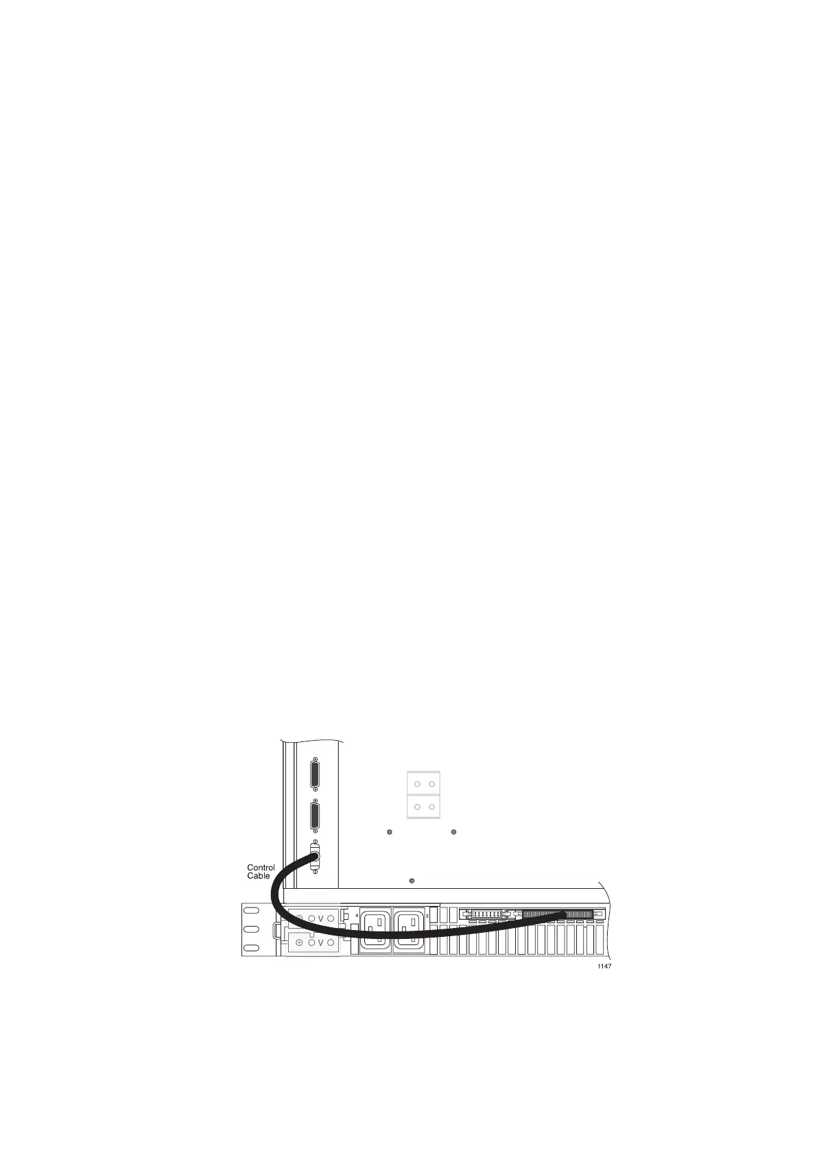
11. Connect the control cable from J1 (right-side flat connector) on the shelf to
the chassis connector labeled AC STATUS/CTL.
12. Insert the AC power cords for each power module into connectors 2 and 3
on the shelf.
31
27/153 30-CRA 119 1170/1 Uen A | 2010-04-09