ESAB CUTMASTER 80
SERVICE Manual 0-5396
5T-2
5T.02 Inspection and Replacement
of Consumable Torch Parts
WARNING
Disconnect primary power to the
system before disassembling the
torch or torch leads.
DONOTtouchanyinternaltorch
parts while the AC indicator light of
thePowerSupplyisON.
Removetheconsumabletorchpartsasfollows:
NOTE!
The shield cup holds the tip and
starter cartridge in place. Position
the torch with the shield cup facing
upwardtopreventthesepartsfrom
fallingoutwhenthecupisremoved.
1. Unscrewandremovetheshieldcupfromthe
torch.
NOTE!
Slag built up on the shield cup that
cannotberemovedmayeffectthe
performance of the system.
2. Inspect the cup for damage. Wipe it clean or
replace if damaged.
Art # A-08067
Shield Cups
3. On torches with a shield cup body and a shield
capordeector,ensurethatthecapordeector
is threaded snugly against the shield cup body.
Inshieldeddragcuttingoperations(only),there
may be an O-ring between the shield cup body
and drag shield cap. Do not lubricate the O-ring.
Shield
Cup Body
O-Ring No. 8-3488
Art # A-03878
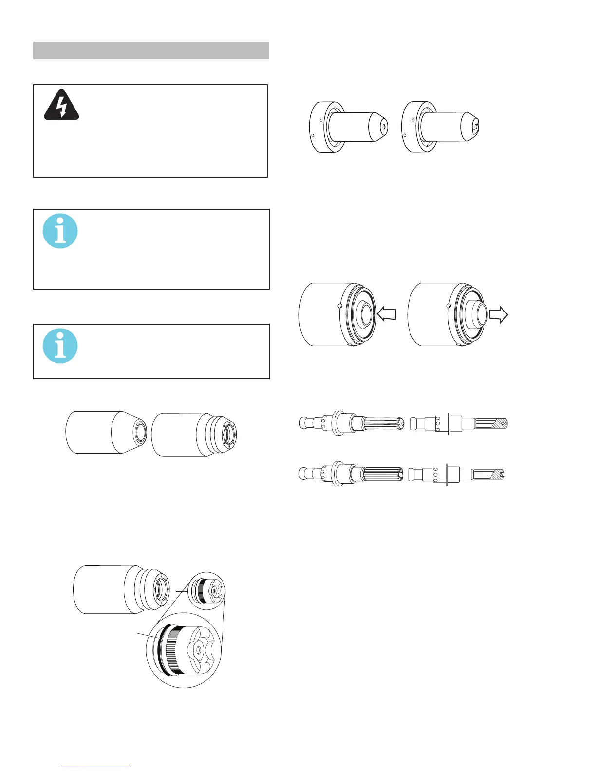
4. Removethetip.Checkforexcessivewear
(indicatedbyanelongatedoroversizedorice).
Clean or replace the tip if necessary.
Example of Tip Wear
5. Removethestartercartridge.Checkforexces-
sivewear,pluggedgasholes,ordiscoloration.
Checkthelowerendttingforfreemotion.Re-
place if necessary.
Art # A-08064_AC
Lower End Fitting
Full Compression
Spring-Loaded
Lower End Fitting at Reset
Full Extension
6. Pull the Electrode straight out of the Torch Head.
Check thefaceoftheelectrodeforexcessive
wear.Refertothefollowinggure.
Worn Electrode
New Electrode
Art # A-03284
Electrode Wear
7. Reinstall the Electrode by pushing it straight into
the torch head until it clicks.
8. Reinstall the desired starter cartridge and tip into
the torch head.
9. Hand tighten the shield cup until it is seated on
the torch head. If resistance is felt when installing
thecup,checkthethreadsbeforeproceeding.
This completes the parts replacement procedures.