ESAB CUTMASTER 80
OPERATION Manual0-5396
4T-6
7. Clean spatter and scale from the shield cup and
the tip as soon as possible. Spraying the shield
cup in anti - spatter compound will minimize the
amount of scale which adheres to it.
Cuttingspeeddependsonmaterial,thickness,andthe
operator’s ability to accurately follow the desired cut line.
Thefollowingfactorsmayhave animpacton system
performance:
• Torchpartswear
• Airquality
• Linevoltageuctuations
• Torchstandoffheight
• Properworkcableconnection
4T.05 Gouging
!
WARNING
Be sure the operator is equipped
withpropergloves,clothing,eyeand
ear protection and that all safety pre-
cautions at the front of this manual
havebeenfollowed.Makesureno
part of the operator’s body comes in
contact with the workpiece when the
torchisactivated.
Disconnect primary power to the
system before disassembling the
torch,leads,orpowersupply.
!
CAUTION
Sparks from plasma gouging can
causedamagetocoated,paintedor
othersurfacessuchasglass,plas-
tic,andmetal.
Check torch parts. The torch parts
must correspond with the type of
operation.RefertoSection4T.07,
Torch Parts Selection.
Gouging Parameters
Gouging performance depends on parameters such
astorchtravelspeed,currentlevel,leadangle(the
anglebetweenthetorchandworkpiece),andthedis-
tance between the torch tip and workpiece (standoff).
!
CAUTION
Touching the torch tip or shield cup
to the work surface will cause exces-
sivepartswear.
Torch Travel Speed
NOTE!
Refer to Appendix Pages for addi-
tional information as related to the
Power Supply used.
Optimumtorchtravelspeedisdependentoncurrent
setting,leadangle,andmodeofoperation(handor
machine torch).
Current Setting
Currentsettingsdependontorchtravelspeed,
modeofoperation(handormachinetorch),andthe
amountofmaterialtoberemoved.
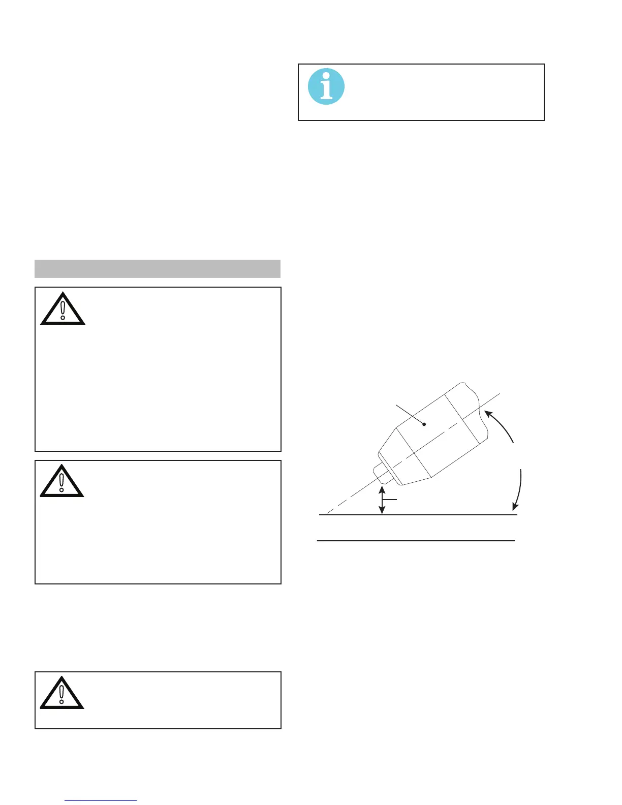
Lead Angle
The angle between the torch and workpiece depends
ontheoutputcurrentsettingandtorchtravelspeed.
The recommended lead angle is 35°. At a lead angle
greater than 45° the molten metal will not be blown
out of the gouge and may be blown back onto the
torch.Iftheleadangleistoosmall(lessthan35°),
lessmaterialmayberemoved,requiringmorepass-
es.Insomeapplications,suchasremovingwelds
orworkingwithlightmetal,thismaybedesirable.
35°
Workpiece
Torch Head
Standoff Height
A-00941_AB
Gouging Angle and Standoff Distance
Standoff Distance
The tip to work distance affects gouge quality and
depth. Standoff distance of 1/8 - 1/4 inch (3 - 6
mm)allowsforsmooth,consistentmetalremoval.
Smallerstandoffdistancesmayresultinaseverance
cut rather than a gouge. Standoff distances greater
than 1/4 inch (6 mm) may result in minimal metal
removalorlossoftransferredmainarc.