ESAB CUTMASTER 80
INSTALLATION Manual0-5396
3-2
5. Pass the cable being used through the access
opening in the back panel of the power supply.
RefertoSection2forpowercablespecications.
!
CAUTION
The primary power source and pow-
er cable must conform to local elec-
trical code and the recommended
circuit protection and wiring require-
ments (refer to table in Section 2).
6. Connect the wires as follows.
• Set Jumper wiresonthe contactor. See il-
lustration.
• Green/YellowwiretoGround.
• RemainingwirestoL1,L2andL3input.It
does not matter what order these wires are
attached.Seethepreviousillustrations.
7. Withalittleslackinthewires,tightenthethrough
- hole protector to secure the power cable.
8. ReinstallthePowerSupplycoverperinstructions
found in section 5.
9. Connecttheoppositeendofindividualwiresto
a customer supplied plug or main disconnect.
10. Connect the input power cable (or close the main
disconnect switch) to supply power.
3.04 Gas Connections
Connecting Gas Supply to Unit
The connection is the same for compressed air or high
pressure cylinders. Refer to the following two subsec-
tionsifanoptionalairlinelteristobeinstalled.
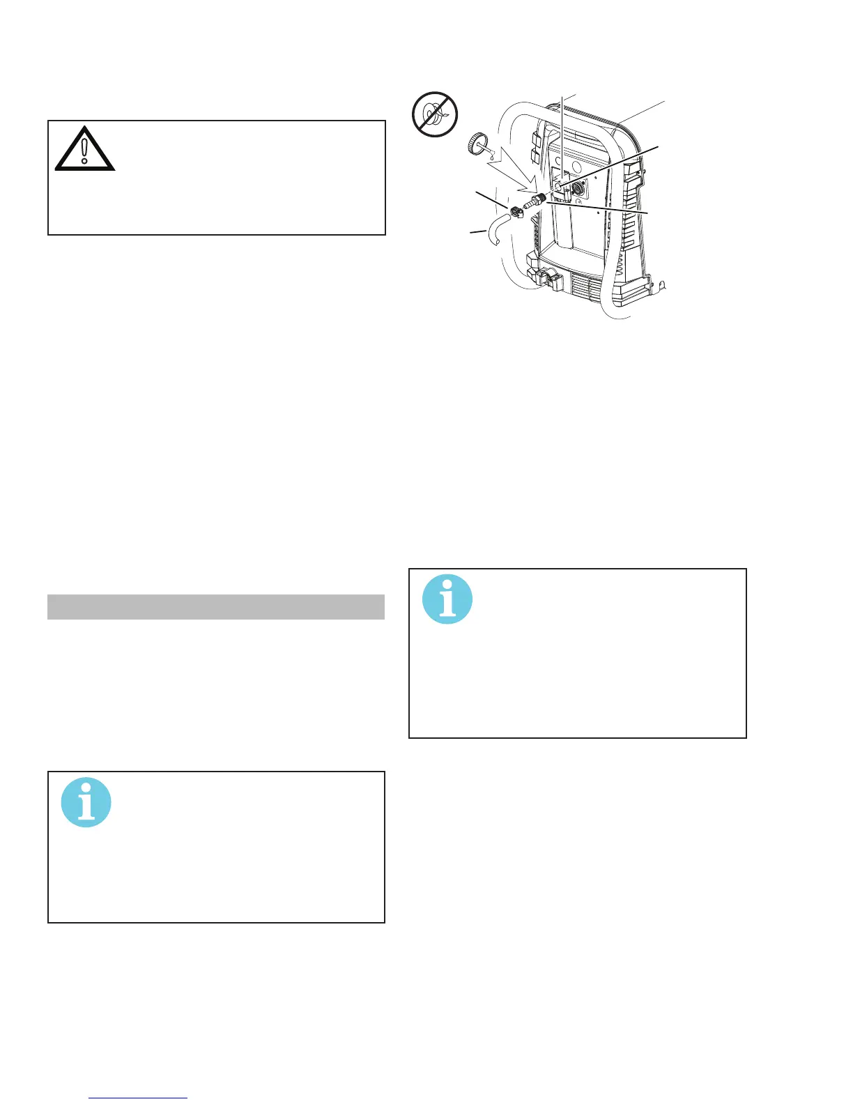
1. Connect the air line to the inlet port. The illustra-
tionshowstypicalttingsasanexample.
NOTE!
Forasecureseal,applythread
sealanttothettingthreads,accord-
ing to manufacturer's instructions.
DonotuseTeontapeasathread
sealer,assmallparticlesofthetape
may break off and block the small air
passages in the torch.
Art # A-07943
Hose Clamp
Assembly
Inlet Port
Gas Supply
Hose
1/4 NPT or ISO-R
to 1/4” (6mm) Fitting
Air Connection to Inlet Port
Installing Optional Single - Stage Air Filter
Anoptionallterkitisrecommendedforimprovedlter-
ingwithcompressedair,tokeepmoistureanddebris
out of the torch.
1. Attach the Single - Stage Filter Hose to the Inlet
Port.
2. AttachtheFilterAssemblytothelterhose.
3. Connect the air line to the Filter. The illustration
showstypicalttingsasanexample.
NOTE!
Forasecureseal,applythreadseal-
anttothettingthreads,according
tothemaker'sinstructions.DoNot
useTeontapeasathreadsealer,
as small particles of the tape may
break off and block the small air
passages in the torch. Connect as
follows: