ESAB CUTMASTER 80
SERVICE Manual 0-5396
5-6
5.06 Power Supply Basic Parts
Replacement
!
WARNING
Disconnect primary power to the
system before disassembling the
torch,leads,orpowersupply.
This section describes procedures for basic parts
replacement. For more detailed parts replacement
procedures,refertothePowerSupplyServiceManual.
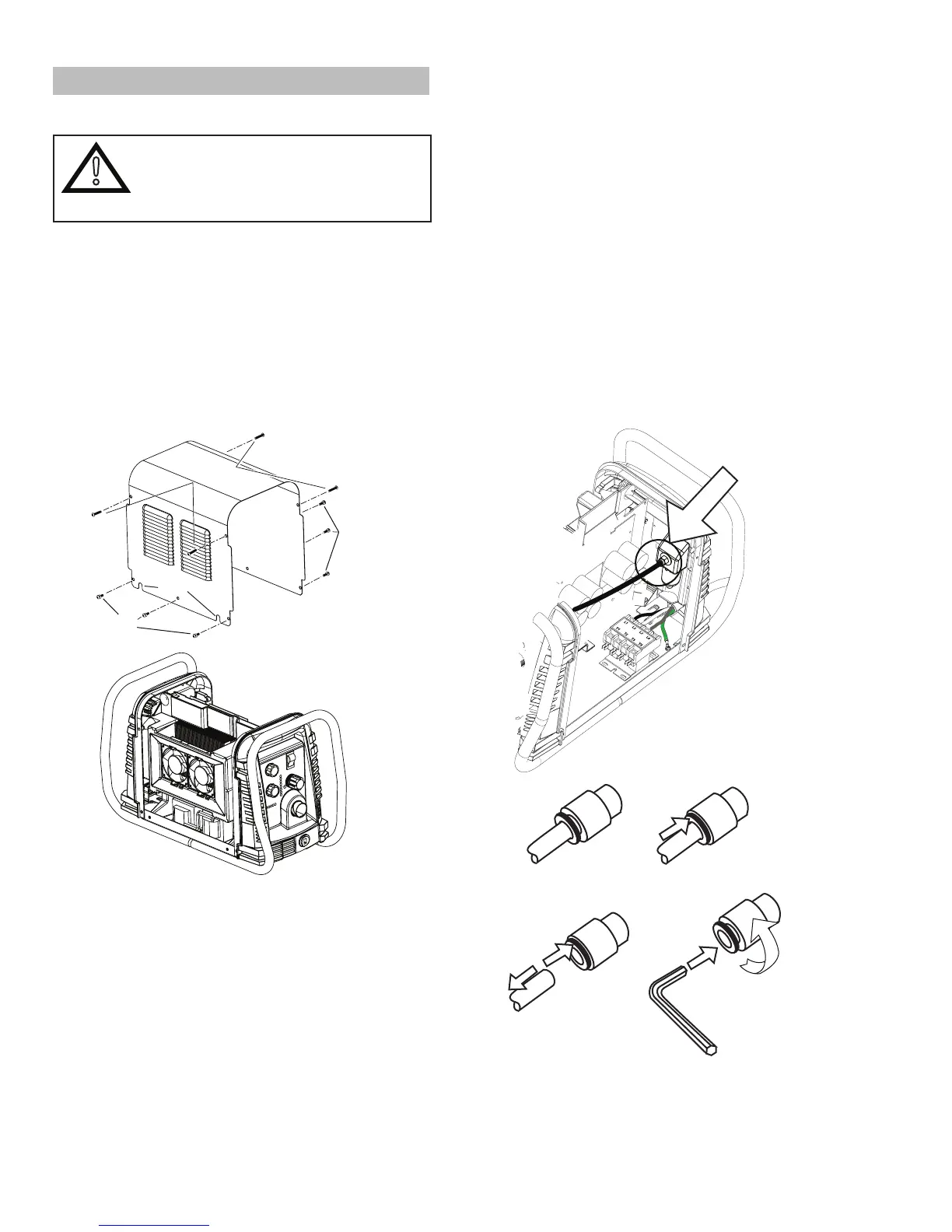
A. Cover Removal
1. Remove the NOTE screws which secure the
covertothemainassembly.Donotloosenthe
lower screws inside the cut out slots in the bottom
ofthecover.
Upper
Screws
Lower
Screws
Lower
Screws
Art # A-07947
Slots
2. CarefullypulltheCoverupandawayfromthe
unit.
B. Cover Installation
1. Reconnectthegroundwire,ifnecessary.
2. Placethecoverontothepowersupplysothat
slotsinthebottomedgesofthecoverengage
the lower screws.
3. Tighten lower screws.
4. Reinstall and tighten the upper screws.
C. Filter Element Assembly Replacement
The Filter Element Assembly is in the rear panel. For
bettersystemperformance,thelterelementshouldbe
checked per the Maintenance Schedule (Subsection
5.02),andeithercleanedorreplaced.
1. Removepowerfromthepowersupply;turnOFF
the gas supply and bleed down the system.
2. Removethesystemcover.See"ACoverRe-
moval"inthissection.
3. Locatetheinternalairlineandthettingfrom
thelterassembly.Number1inthefollowing
illustration.
4. Hold a wrench or similar tool against the locking
ringonthelterassemblytting,then pull on
thehosetoreleaseit.(Numbers2and3inthe
following illustration).
Art # A-07989
1
2
3
4
5
6mm
5. Removethettingfrom the lter element as-
sembly by inserting a 6 mm hex wrench into the
internalhexttingandturningitcounterclock-
wise (left). Numbers 4 and 5 in the previous
illustration.