ESAB CUTMASTER 80
Manual0-5396 INSTALLATION
3-1
SECTION 3 SYSTEM:
INSTALLATION
3.01 Unpacking
1. Use the packing lists to identify and account for
each item.
2. Inspect each item for possible shipping damage.
Ifdamageisevident,contactyourdistributorand
/ or shipping company before proceeding with the
installation.
3. Record Power Supply and Torch model and serial
numbers,purchasedateandvendorname,inthe
information block at the front of this manual.
3.02 Lifting Options
The Power Supply includes a handle for hand lifting
only. Be sure unit is lifted and transported safely and
securely.
WARNING
Donottouchliveelectricalparts.
Disconnect input power cord before
movingunit.
!
WARNING
FALLINGEQUIPMENTcancause
seriouspersonalinjuryandcandam-
age equipment.
HANDLEisnotformechanicallifting.
• Onlypersonsofadequatephysicalstrengthshould
lift the unit.
• Liftunitbythehandles,usingtwohands.Donot
use straps for lifting.
• Use optional cartor similar device ofadequate
capacitytomoveunit.
• Placeunitonaproperskidandsecureinplace
beforetransportingwithaforkliftorothervehicle.
3.03 Primary Input Power
Connections
!
CAUTION
Check your power source for cor-
rectvoltagebeforeplugginginor
connecting the unit. The primary
powersource,fuse,andanyexten-
sion cords used must conform to
local electrical code and the recom-
mended circuit protection and wiring
requirementsasspeciedinSection
2.
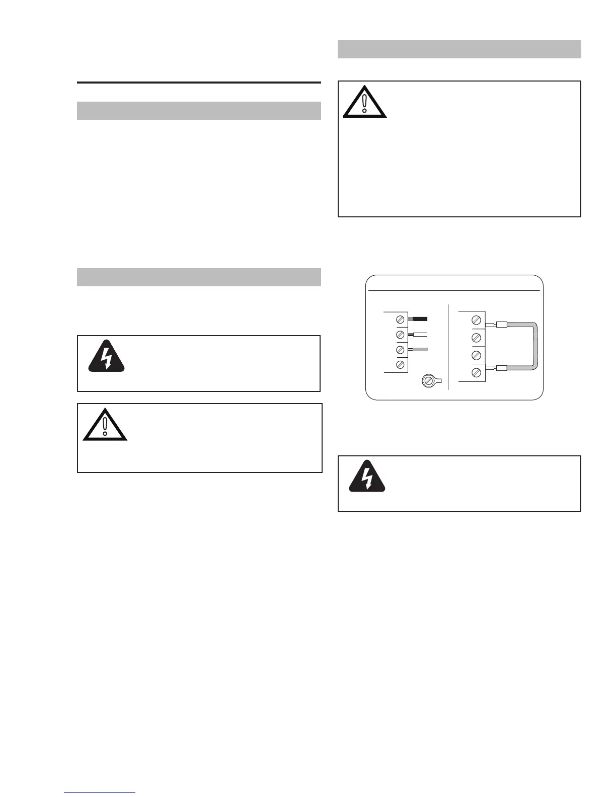
All units are shipped from the factory with a 380/400Volt
input power cable wired to the input contactor in the
three- phaseconguration. Thefollowingillustration
and directions are for replacing the input power cable.
Art # A-08546
Three-Phase (3ø) and Jumper Settings
L1
L2
L3
L4
Jumper L1 -L4
L1
L2
L3
GND
L4
Three Phase Input Power Wiring
A. Connections to Three Phase Input
Power
WARNING
Disconnect input power from the
power supply and input cable before
attempting this procedure.
These instructions are for replacing a 380/400V input
power cable to the Power Supply for Three - Phase
input power.
1. RemovethePowerSupplycoverperinstructions
found in section 5.
2. Disconnect the original input power cable from
the main input contactor and the chassis ground
connection.
3. Loosen the through - hole protector on the back
panel of the power supply. Pull the original power
cable out of the power supply.
4. Using a customer supplied four - conductor input
powercableforthevoltagedesired,stripback
theinsulationontheindividualwires.