ESAB CUTMASTER 80
SERVICE Manual 0-5396
5-4
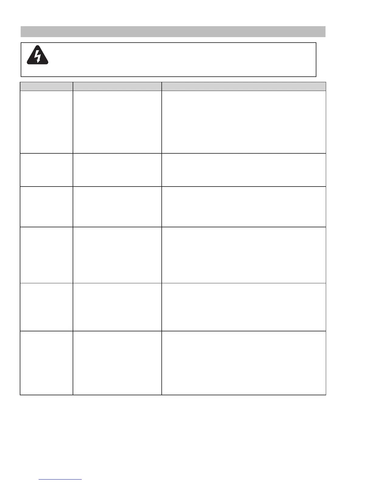
5.05 Basic Troubleshooting Guide
WARNING
Thereareextremelydangerousvoltageandpowerlevelspresentinsidethisunit.Do
notattempttodiagnoseorrepairunlessyouhavehadtraininginpowerelectronics
measurement and troubleshooting techniques.
Problem - Symptom Possible Cause Recommended Action
ON/OFFSwitch
isONbuttheA/C
Indicator does not
light
1. Primary power disconnect is in
OFF position.
2. Primary fuses / breakers are
blown or tripped.
3. Units internal fuse blown.
4. Faulty components in unit.
1.TurnprimarypowerdisconnectswitchtoONposition.
2.a)Havequaliedpersoncheckprimaryfuses/breakers.
b) Connect unit to known good primary power receptacle
3. a) Replace fuse.
b)Iffuseblowsagain,returntoauthorizedservicecenterfor
repair or replacement.
4.Returntoauthorizedservicecenterforrepairorreplacement.
Fault indicator
ashing,65PSI
indicatorashing
1.Improperinputvoltage.
2.Primaryinputvoltageproblem.
3. Faulty components in unit.
1.Checkforproperprimaryinputvoltage.
2.Havequaliedpersoncheckprimaryvoltagetoinsureitmeets
unit requirements see section 2.05.
3.Returntoauthorizedservicecenterforrepairorreplacement.
TEMPERATURE
indicatorON.FAULT
indicatorashing.
1.Airowthroughoraroundtheunit
is obstructed.
2. Duty cycle of the unit has been
exceeded
3. Failed components in unit
1. Refer to clearance information – section 2.04
2. Allow unit to cool.
3.Returntoauthorizedservicecenterforrepairorreplacement.
GASLEDOFF,
FAULTandMIN
pressure indicators
ashing.
1. Gas supply not connected to unit.
2.GassupplynotturnedON.
3. Gas supply pressure too low.
4.AIRPRESSURECONTROL
regulator set too low.
5. Failed components in unit.
1. Connect gas supply to unit.
2.TurngassupplyON.
3. Set air supply inlet pressure to unit to 120 psi.
4.Adjustregulatortosetairpressure-seesection4.02.
5.Returntoauthorizedservicecenterforrepairorreplacement.
FAULT and 70 PSI
indicatorsashing.
1. Shield Cup loose.
2. Torch not properly connected to
power supply.
3. Problem in torch and leads PIP
circuit.
4. Failed components in unit.
1. Hand tighten the shield cup until it is snug.
2. Insure torch ATC is securely fastened to unit.
3.Replacetorchandleadsorreturntoauthorizedservicecenter
for repair or replacement.
4.Returntoauthorizedservicecenterforrepairorreplacement.
FAULT and 75 PSI
indicatorsashing.
1.StartsignalisactivewhenON/
OFFSWITCHisturnedtoON
position.
2. Problem in the torch and leads
switch circuit.
3. Failed components in unit.
1.Startcanbeactiveforoneofthefollowing:
•Handtorchswitchheldclosed
•Handpendantswitchheldclosed
•CNCSTARTsignalisactivelow
Release the START signal source
2.Replacetorchandleadsorreturntoauthorizedservicecenter
for repair or replacement.
3.Returntoauthorizedservicecenterforrepairorreplacement.