ESAB CUTMASTER 80
Manual0-5396 OPERATION
4-1
SECTION 4 SYSTEM:
OPERATION
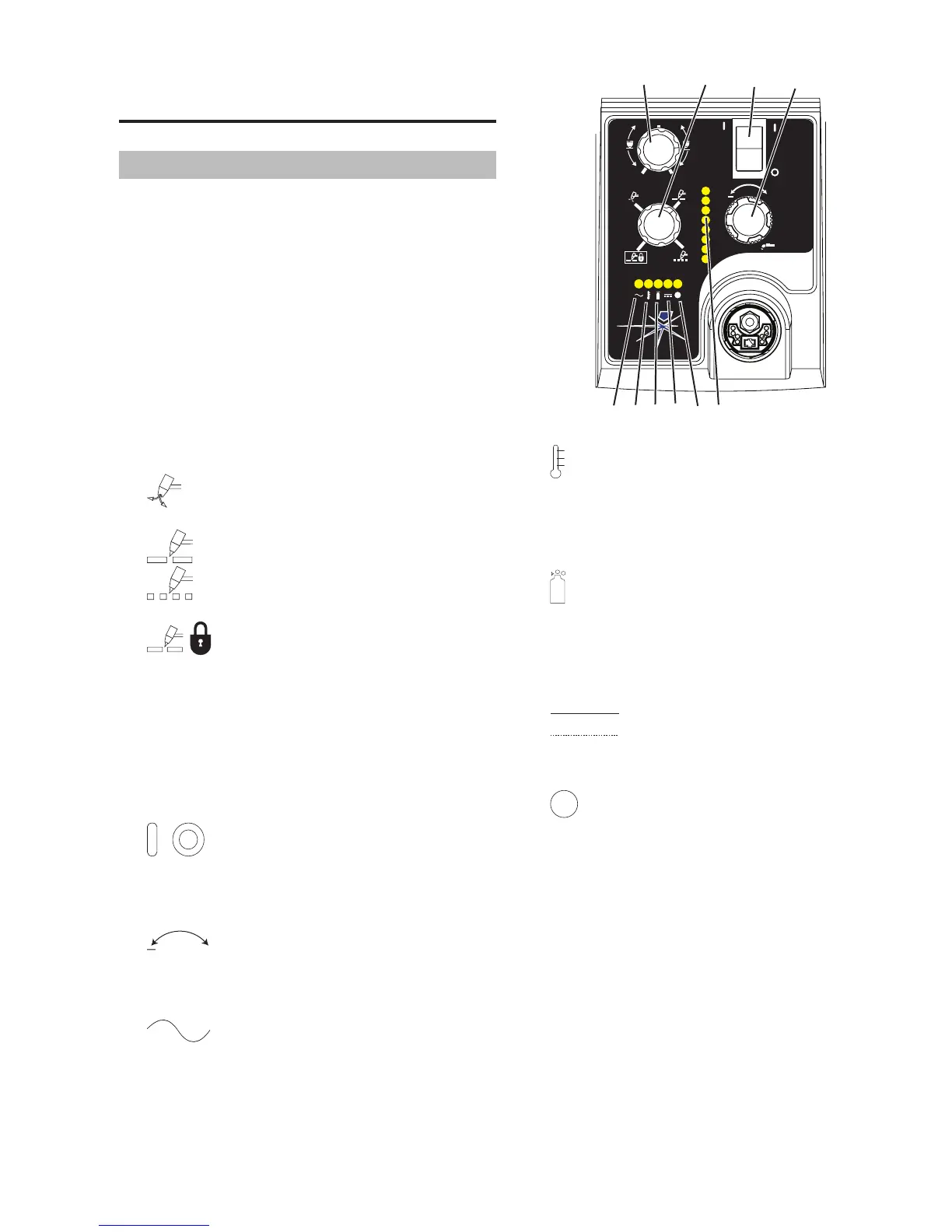
4.01 Front Panel Controls /
Features
SeeIllustrationfornumberingIdentication
1. Output Current Control
Sets the desired output current. Output settings
up to 60 Amps may be used for drag cutting (with
the torch tip contacting the workpiece) or higher for
standoff cutting.
2. Function Control
FunctionControlKnob,Usedtoselectbetweenthe
different operating modes.
SET Used to purge the air through the unit
and torch and leads and to adjust gas pressure.
RUN Used for general cutting operations
RAPID AUTO RESTART Allows for faster
restarting of the Pilot Arc for uninterrupted cutting.
LATCH Used for longer hand held cuts.
Onceacuttingarcisestablished,thetorchswitch
canbereleased.ThecuttingarcwillremainONuntil
thetorchisliftedawayfromtheworkpiece,thetorch
leavestheedgeoftheworkpiecethetorchswitch
isactivatedagainorifoneofthesysteminterlocks
isactivated.
3. ON OFF Power Switch
/ ON/OFFSwitchcontrolsinputpowerto
thepowersupply.UpisON,downisOFF.
4. Air/Gas Pressure Control
+
The Pressure Control is used in the "SET"
modetoadjusttheair/gaspressure.Pulltheknob
outtoadjustandpushintolock.
5. AC Indicator
Steady light indicates power supply is ready for op-
eration.Blinkinglightindicatesunitisinprotective
interlockmode.ShutunitOFF,shutOFFordiscon-
nectinputpower,correctthefault,andrestartthe
unit. Refer to Section 5 for details.
A
+
PSI BAR
MAXMAX
MINMIN
!
4
5
6
7
8
9
Art# A-07886
MIN
MAX
10
6. Temp Indicator
IndicatorisnormallyOFF. Indicator is ON when
internal temperature exceeds normal limits. Let the
unit cool before continuing operation.
7. Gas Indicator
IndicatorisONwhenminimuminputgaspressure
for power supply operation is present. Minimum
pressureforpowersupplyoperationisnotsufcient
for torch operation.
8. DC Indicator
IndicatorisONwhenDCoutputcircuitisactive.
9.
Fault Error Indicator
IndicatorisONwhenFaultcircuitisactive.Seesec-
tion 5 for explanations of fault lights.