4 INSTALLATION
0463 751 001
- 22 -
© ESAB AB 2023
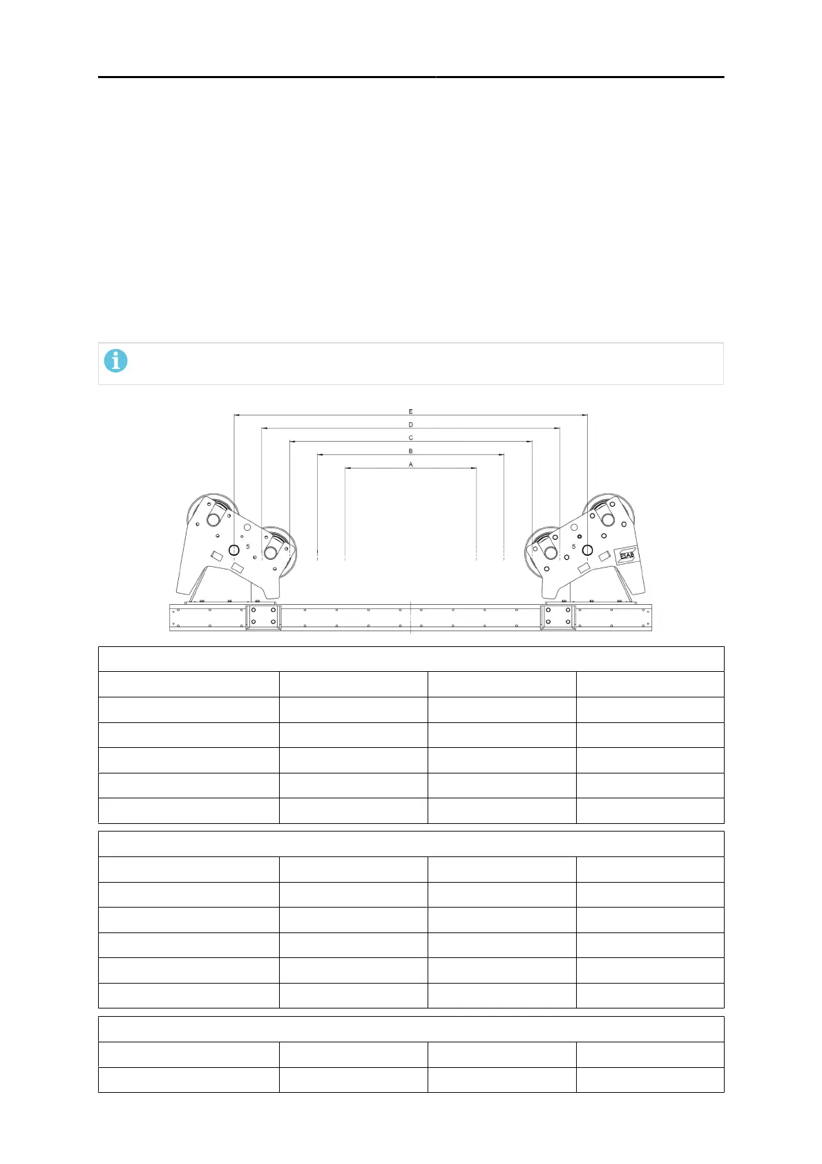
4.3 Adjusting the wheel stands
The positions of the two wheel stands on the base frame must be adjusted to load vessels of different
diameters.
1. Unbolt the wheel stand from the base frame.
2. Use an overhead crane to lift the wheel stand using the lifting points.
3. Move the wheel stand to the required position for the diameter of the vessel.
4. Bolt the wheel stands back onto the base frame using all the bolts, and tighten to the correct torque
i.e. M12 (8.8) 81 Nm and M16 (8.8) 197 Nm.
5. See tables and the picture below for correct distances between the two wheels stands.
Suitable centre to centre distance (C -C) in relation to workpiece diameter
NOTE!
Only when the workpiece is resting an all wheels.
ESD 7.5, ESI 7.5
Wheelstandposition C- C (mm) Min object Ø (mm) Max object Ø (mm)
A 650 950 1320
B 910 1320 1990
C 1170 1960 2670
D 1430 2480 3340
E 1690 3000 4000
ESD 15, ESI 15
Wheelstandposition C- C (mm) Min object Ø (mm) Max object Ø (mm)
A 760 1090 1540
B 1140 1540 2510
C 1520 2510 3500
D 1900 3400 4400
E 2280 4100 5400
ESD 30, ESI 30
Wheelstandposition C- C (mm) Min object Ø (mm) Max object Ø (mm)
A 995 1420 2080