5 OPERATION
0463 751 001
- 27 -
© ESAB AB 2023
5 OPERATION
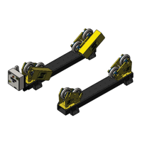
5.1 Roller bed details
The roller bed set usually consists of one drive unit and one, two or, three idler units.
The idler unit consists of a base frame with two wheel stands bolted onto the top of it. Holes are drilled
through the top of the base frame for the wheel stands to be positioned at different distances to suit
the vessel diameter.
The drive unit consists of two-wheel stands that can be positioned to suit the vessel diameter. Both
wheel stands are motorized. The wheel is turned by a gear motor mounted straight onto the drive
shaft.
Inside the control panel is an inverter that controls the motors.
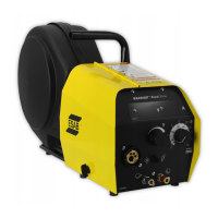
The roller bed is manually controlled via a wireless remote - control pendant. It can also be connected
to a welding manipulator, for example, ESAB CaB, and then controlled by the CaB controller.
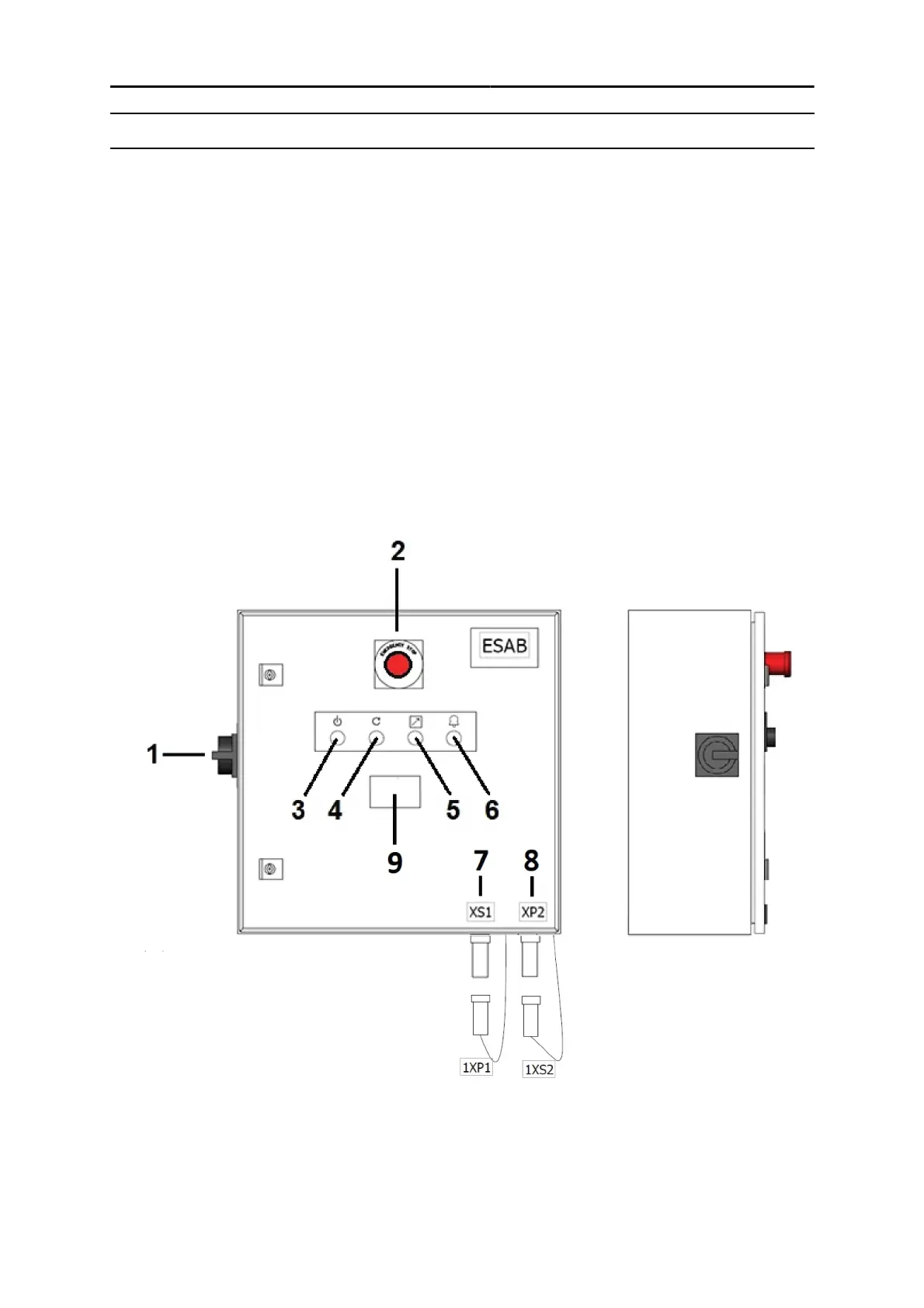
5.2 Control panel
1. Mains switch (A1) 6. Alarm lamp/pushbutton (A33)
2. Emergency stop button (A30) 7. Connector to external control (XS1)
3. Mains ON lamp (A32) 8. Connector to the next roller bed unit (XP2)
4. E-stop reset pushbutton (A31) 9. Digital display (A35) (optional)
5. White lamp (A34)
 Loading...