4 INSTALLATION
0463 751 001
- 23 -
© ESAB AB 2023
ESD 30, ESI 30
B 1375 2080 2990
C 1755 2910 3900
D 2135 3700 4900
ESD 60, ESI 60
Wheelstandposition C- C (mm) Min object Ø (mm) Max object Ø (mm)
A 995 1420 2010
B 1415 2010 3090
C 1835 3070 4100
D 2255 3900 5200
E 2675 4800 6300
ESD 90, ESI 90, ESI 120, ESI 120
Wheelstandposition C- C (mm) Min object Ø (mm) Max object Ø (mm)
A 1470 2120 2990
B 1890 2930 4000
C 2310 3800 5100
D 2730 4600 6200
NOTE!
Adjust the wheel stands so that the axis of rotation of the vessel is on the centre line of the
drive and idler frames.
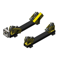
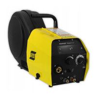
4.4 Adjusting the included angle
The included angle (α) is the angle between two lines from the centre of the rotation axis of the vessel
to the centre of each wheel on the drive or idler section. As the angle increases, so do the resulting
load on each wheel, and consequently, the load on the bearings. Also, by increasing the angle, more
torque, therefore more power is required to rotate the vessel.
The distance between the wheel stands, on both the drive unit and the idler units depends on the
diameter of the vessel. To achieve a safe and smooth operation of the roller beds the recommendation
is the keep the included angle (α) between 45° and 70°.