2 INTRODUCTION
0463 751 001
- 8 -
© ESAB AB 2023
2 INTRODUCTION
This Instruction manual describes the use and maintenance of the self-aligning roller beds, referred to
as roller beds in this document. Actions that must be carried out by the manufacturer are not included
in this manual.
This manual is part of the roller beds. Keep a copy of the manual with the roller beds and the original
in a safe place. If the roller beds are sold, supply the manual with it.
The pictures and diagrams used in this manual are for illustrative purposes only to help explain
instructions in the text. The equipment supplied may differ slightly.
2.1 Equipment
The roller bed drive is supplied with:
• Drive units
• Mounted control cabinet
• Wireless remote - control pendant
• Base frame
• Instruction manual
The roller bed idler is supplied with:
• Idler units
• Base frame
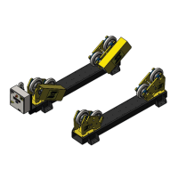
2.2 Purpose and function of roller beds
The roller beds are designed to aid the welding of cylindrical vessels.
By using the independent drive and idler units, vessels of varying lengths can be placed on the roller
beds supported on the roller bed wheels. The wheels can be adjusted on the base frame to
accommodate different vessel diameters.
2.3 Terminology used in this manual
Drive unit Roller bed section with powered wheels.
Idler unit Roller bed section with freewheeling wheels.
Roller bed set A set consists of one drive unit and one or more idler units.
Base frame The frame the drive or idler wheels are mounted on. These are pre-drilled
so that the wheel stands can be positioned for different vessel diameters.
Wheel stand The stand which houses the roller bed wheels. This is bolted down to the
baseframe.
Control panel Electrical control box mounted on the drive unit.
Wireless remote -
control pendant
A wireless operator hand control pendant.
Receiver The receiver that communicates with the wireless remote-control pendant.
Vessel Any component or device that is handled on the roller bed set.