5 OPERATION
0463 751 001
- 28 -
© ESAB AB 2023
Control panel
1. Mains switch (A1).
2. Emergency stop button (A30). Pressing causes loss of function. The button must be released before
reset is possible.
3. Mains ON lamp (A32). Illuminates (green) once power has been turned on and the control system has
started up. (Mains switch (1) is turned to ON position). This pushbutton, in combination with (A33), is
also used for calibration and reset of a second roller bed (RB2) connected to the primary roller bed
(RB1).
4. E-stop reset button (A31). Illuminates (blue) when any of the emergency stop pushbuttons are
activated and/or not reset. It flashes when the e-stop pushbuttons are de-activated again and will go
off when the buttons are pushed (E-stop reset).
5. White lamp (A34). Illuminates after requested control mode has been chosen, either local (illuminates
constantly) or controlled from an external device (flashes), for example, ESAB CaB. Press this
pushbutton to activate local control when the roller bed is used as a standalone unit. Press again to
deactivate it. When the roller bed is connected to and controlled from an ESAB CaB i.e., digital output
from the CaB is set to high, this lamp flashes until the signal is set to low again.
6. Alarm lamp / pushbutton (A33). Illuminates constantly (red) when any kind of fault has occurred. Must
be manually reset after the fault has been detected and fixed. It flashes if battery power is low on the
wireless remote-control pendant and stops flashes when the battery is charged or replaced. This
pushbutton, in combination with (A32), is also used for calibration and reset of a second roller bed
(RB2) connected to the primary roller bed (RB1).
7. Connector to external control, for example, CaB (XS1). A dummy plug with jumpers (1XP1) must be
connected to be able to run the roller bed as a stand-alone unit.
8. Connector to a second roller bed controller i.e., synchronized drives (XP2). A dummy plug with
jumpers (1XS2) must be connected to be able to run the roller bed as either a single unit or when it is
the last unit in a chain of several connected roller beds.
9. Digital display (A35, when applicable). It shows the peripheral rotation speed of the PU wheels.
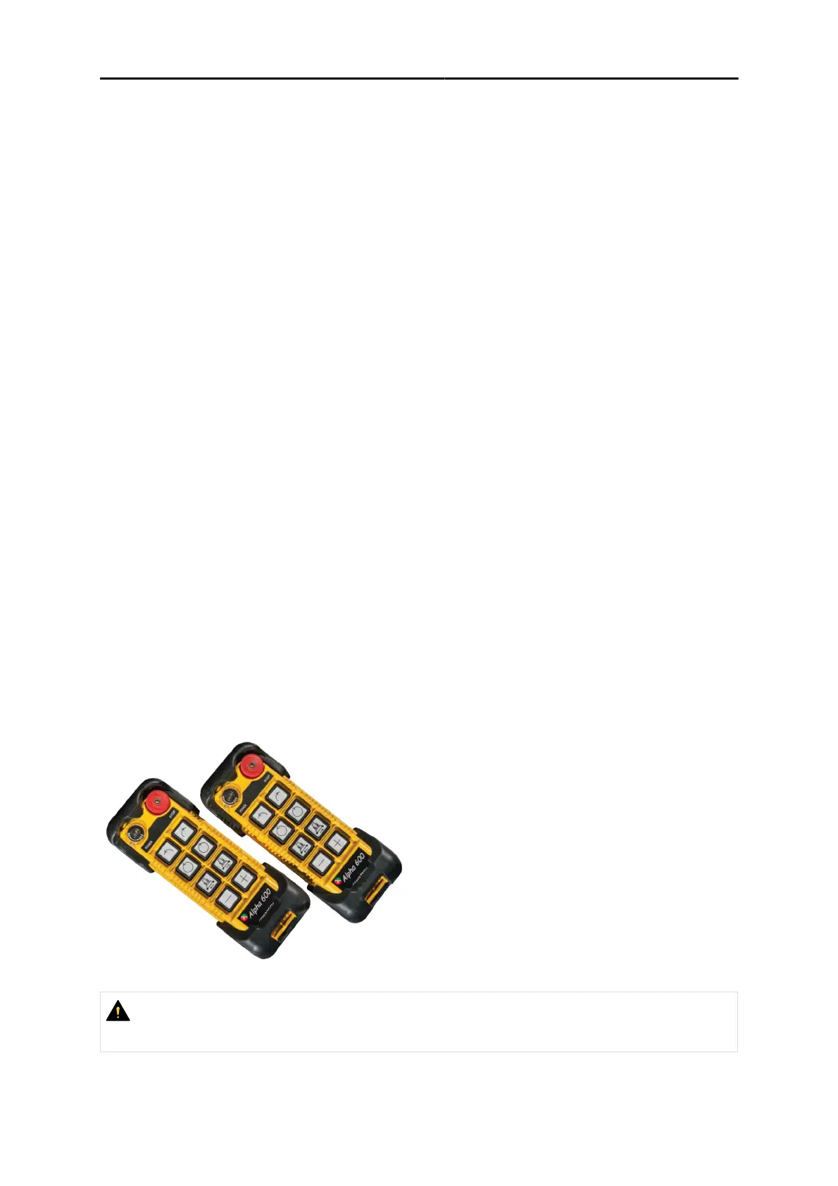
5.3 Wireless remote - control pendant
The system is delivered with two wireless remote-control pendants with rechargeable batteries, one
receiver (mounted behind the control panel), and one inductive charger. The two wireless
remote-control pendants are working on the same radio channel and frequency, and therefore only
one at a time would be used. Ideally, one is used in the operation while the other is connected to the
charger.
CAUTION!
Always stop the rotation before changing direction by pressing the same pushbutton that has
been pressed last for the requested direction.