ESAB FABRICATOR 141i
Manual 0-5448 3-7 SAFETY AND INSTALLATION
!
WARNING
Use the flowmeter/ regulator for the gas
and pressure for which it is designed.
NEVER alter a flowmeter/ regulator for use
with any other gas.
NOTE!
Flowmeters/ Regulators supplied with
5/8" -18 standard inert gas connections.
Flowmeters/ Regulators purchased with
open 1/8”, 1/4”, 3/8”, or 1/2” NPT ports
must be assembled to their intended
system.
1. Note the maximum inlet pressure stamped on the
flowmeter/ regulator. DO NOT attach the flowmeter/
regulator to a system that has a higher pressure than
the maximum rated pressure stamped on the flowme-
ter/ regulator.
2. The flowmeter/ regulator body will be stamped “IN” or
“HP” at the inlet port. Attach the inlet port to the system
supply pressure connection.
3. If gauges are to be attached to the flowmeter/ regulator
and the flowmeter/ regulator is stamped and listed by
a third party (i.e. “UL” or “ETL”). The following require-
ments must be met:
a) Inlet gauges over 1000 PSIG (6.87 mPa) shall con-
form with the requirements of UL 404, “Indicating
Pressure Gauges for Compressed Gas Service.”
b) Low pressure gauges must be UL recognized for
the class of flowmeter/ regulator they are being
used on according to UL252A.
!
WARNING
DO NOT use a flowmeter/ regulator that
delivers pressure exceeding the pres-
sure rating of the downstream equipment
unless pro visions are made to prevent
over-pressurization (i.e. system relief
valve). Make sure the pressure rating of
the down stream equipment is compatible
with the maximum delivery pressure of the
flowmeter/ regulator.
4. Be sure that the flowmeter/ regulator has the correct
pressure rating and gas service for the cylinder used.
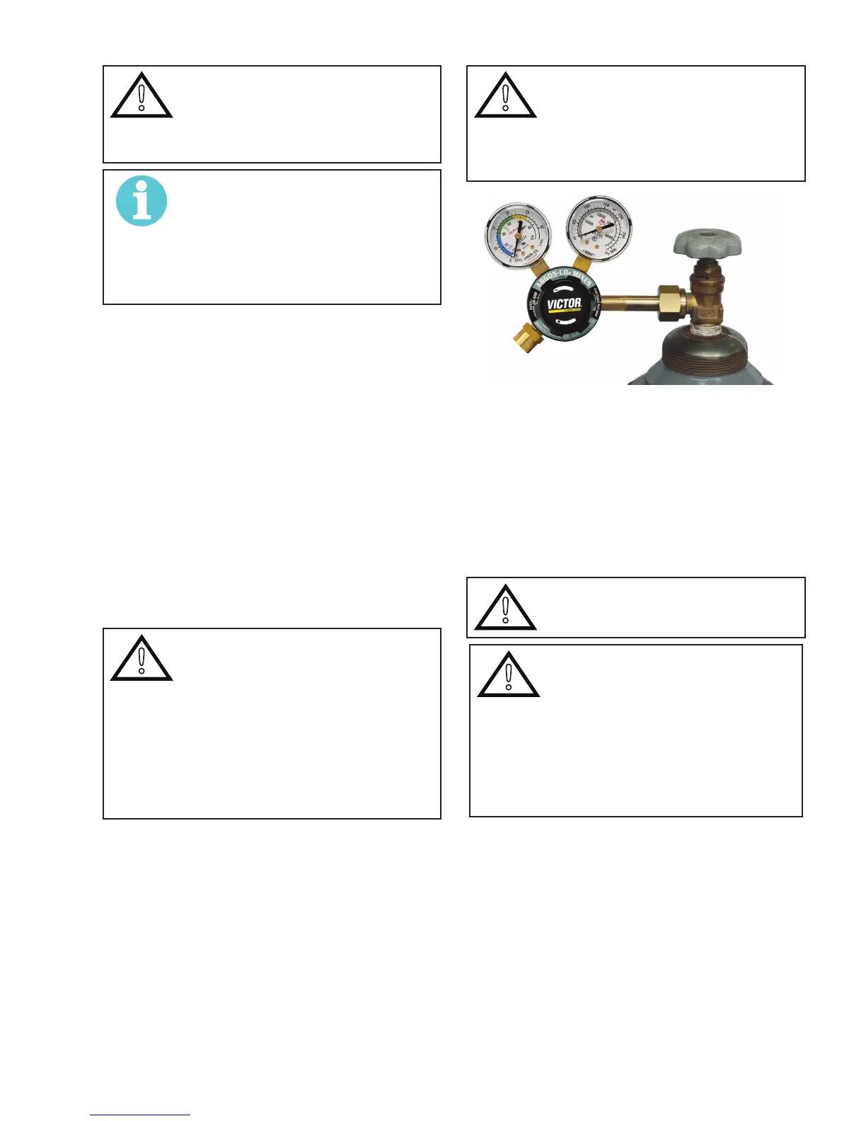
5. Carefully inspect the flowmeter/ regulator for dam-
aged threads, dirt, dust, grease, oil, or other flammable
substances. Remove dust and dirt with a clean cloth. Be
sure the inlet swivel filter is clean and in place. Attach
the flowmeter/ regulator (Figure 3-2) to the cylinder
valve. Tighten securely with a wrench.
!
WARNING
DO NOT attach or use the flowmeter/ regu-
lator if oil, grease, flamma ble substances
or damage is present! Have a qualified
repair technician clean the flowmeter/
regulator or repair any damage.
A-09845_AB
Figure 3-2: Flowmeter/ Regulator to Cylinder Valve
6. Before opening the cylinder valve, turn the flowmeter/
regulator adjusting screw counterclockwise until there
is no pressure on the adjusting spring and the screw
turns freely.
7. Relief Valve (where provided): The relief valve is de-
signed to protect the low pressure side of the flowme-
ter/ regulator from high pres sures. Relief valves are not
intended to protect down stream equipment from high
pressures.
!
WARNING
DO NOT tamper with the relief valve or
remove it from the flowmeter/ regulator.
!
WARNING
Stand to the side of the cylinder opposite
the flowmeter/ regulator when open-
ing the cylinder valve. Keep the cylinder
valve between you and the flowmeter/
regulator. For your safety, NEVER STAND
IN FRONT OF OR BEHIND A FLOWMETER/
REGULATOR WHEN OPENING THE CYLIN-
DER VALVE!
8. Slowly and carefully open the cylinder valve (Figure
3-3) until the maximum pressure shows on the high
pressure gauge.
 Loading...