ESAB FABRICATOR 141i
TROUBLESHOOTING 6-8 Manual 0-5448
6.09 Check Main Input Rectifier
Input Rectifier Testing Multimeter Lead Placement Diode Voltage
AC1 to DC+
Positive meter lead to AC1
Negative meter lead to testpoint DC+
0.2 – 0.8 VDC
AC2 to DC+
Positive meter lead to AC2
Negative meter lead to testpoint DC+
0.2 – 0.8 VDC
AC1 to DC-
Positive meter lead to testpoint DC-
Negative meter lead to testpoint AC1
0.2 – 0.8 VDC
AC2 to DC-
Positive meter lead to testpoint DC-
Negative meter lead to testpoint AC2
0.2 – 0.8 VDC
Table 6-7 IGBT’s, Multimeter set to measure Diode Voltage
Measurements may be made directly onto the main input rectifier. AC1 and AC2 may be measured from the pins on the mains supply
plug with the main power switch set to the ON position.
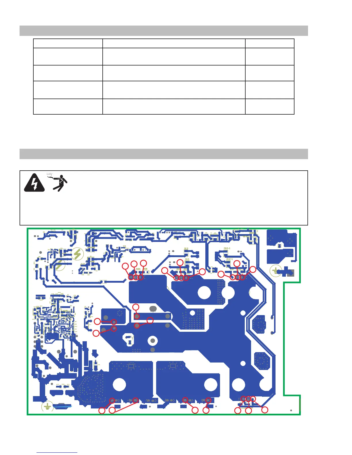
6.10 DC Bus Voltage Measurement
Apply voltage to the Power Source.
WARNING
There are extremely dangerous voltage and power levels present inside these Power Sources. Do
not attempt to diagnose or repair unless you have had training in power electronics measurement
and troubleshooting techniques.
Once power is applied to the Power Source, there are extremely hazardous voltage and power
levels present.
Do not touch any live parts.
Art # A-12171
12
16
20
11
15
19
13
7
1
6 8
2
5
10
14
18
21
9
22
17
 Loading...