ESAB FABRICATOR 141i
Manual 0-5448 6-9 TROUBLESHOOTING
DC Bus Testing Multimeter Lead Placement
Voltage with Supply Voltage ON
Buck CAPACITOR
Negative meter lead to testpoint1
Positive meter lead to testpoint2
161 VDC +/-10%
Table 6-8 DC BUS, Multimeter set to measure DC volts
Note: These DC voltages are at nominal mains supply voltage of 115VAC.
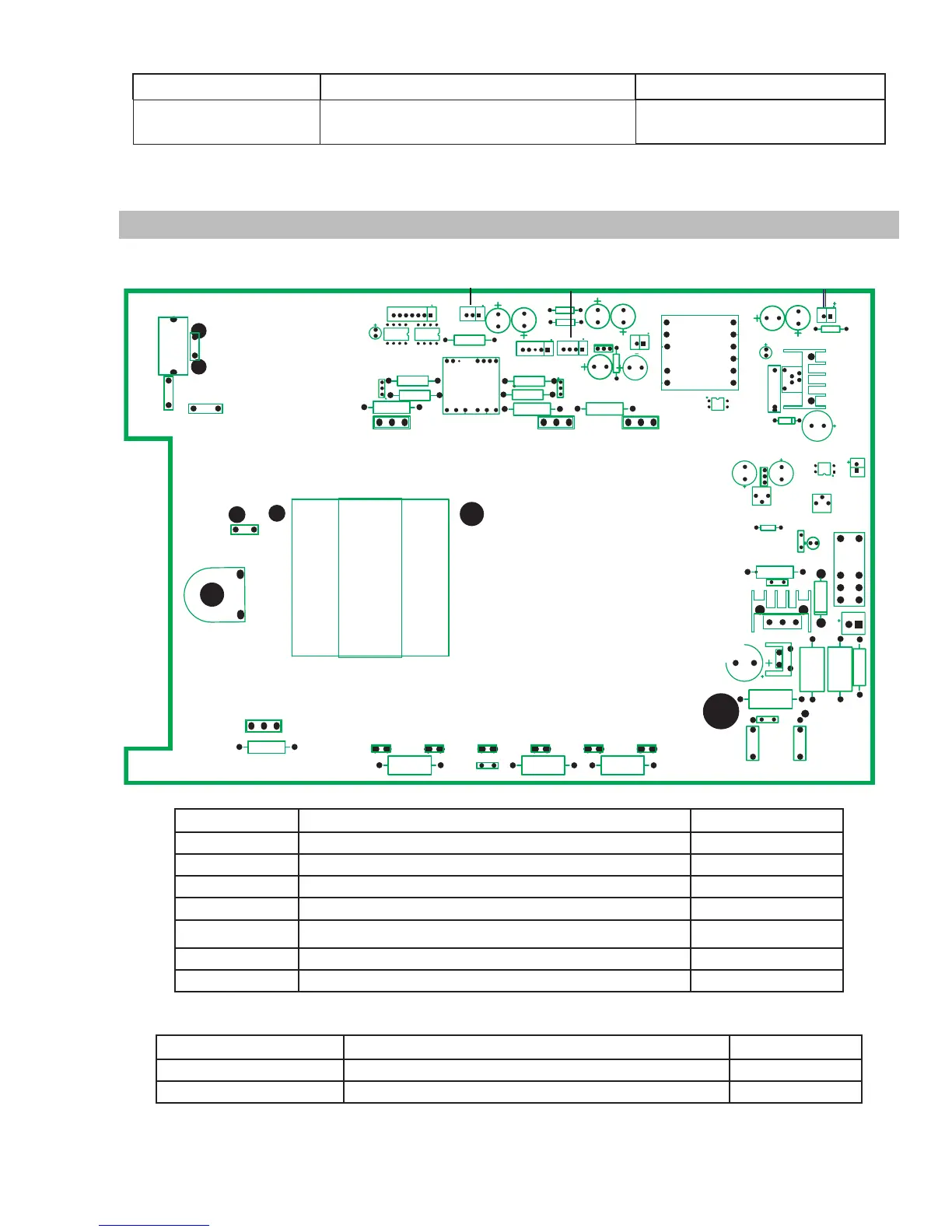
6.11 PCB Connectors
1. Main PCB1
Art # A-12172
AC1
AC2
CIN1
CU3
CU4
T2
T1
R24
IN
DY1
R29
R28
T5
PWM
W05
2
MD
COUT2
COUT1
OUT-
OUT+
T20-1
T13-1
T14-1T15-1
R100R102
C100
T16-1T17-1
R101
DC+
DC-
TR8
QF/FJ
GAS
CY1
R25
T4
AC OUT
AC OUT
IN Header Pin Pin Function Signal
1 +15V +15 VDC
2 IGBT 1, 4 PWM Driver Signal 5 VDC Vpk
3 IGBT 2, 5 PWM Driver Signal 5 VDC Vpk
4 IGBT 2, 5 PWM Driver Signal 5 VDC Vpk
5 IGBT 1, 4 PWM Driver Signal 5 VDC Vpk
6 Rectified Secondary of Current Transformer TR8 -6 VDC
7 Common of +15V 0 VDC
Table 6-9 IN Header Pin Function (Connects to DRIVE header on Control PCB2)
PWM Header Pin Pin Function Signal
1 PWM Common 0 VDC
2 Motor PWM Driver signal 5 V Vpk
Table 6-10 PWM Header Pin Function (Connects to PWM header on Control PCB2)
 Loading...