12
C
Installing the Electricity and Gas to the Appliance
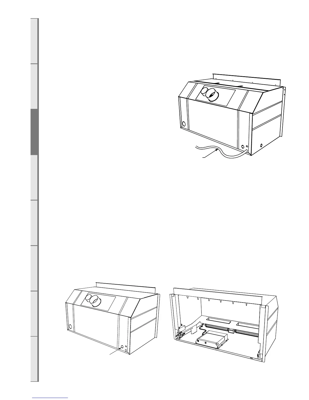
C1 Power Supply
While the cavity is being created, consideration must be given to the location of an
appropriate power supply. An earthed 230/240 volt mains power connection (typically a
standard 3 pin outlet) must be available within 1m of the bottom right of the appliance. This
connection must be accessible after the heater has been fully installed so that the appliance
can be safely disconnected from the mains
power supply prior to servicing.
A mains isolation switch (compliant to
AS:NZS 5601 Clause 6.2.8) which is
accessible from outside the cavity can also
be used to disconnect the power.
Regardless of the method used, it MUST
ALWAYS be possible to safely isolate the
electrical supply to the appliance after it has
been fully installed.
This appliance must not be located
immediately below a socket outlet. This appliance will draw a maximum of 2 Amps from a
230/240V supply. No additional power supply is required for the power flue.
An electrical wiring diagram is located underneath the electronic tray, and also in the rear of this
manual (section S10 on page 54).
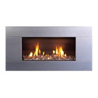
C2 Network Cable
If the appliance is to be wired to a home automation system or internet router/network is being
installed then provision must be made for the network cable to get to the control tray. A plastic
plug is provided on the rear left of the appliance for a network cable to pass through the chassis
and reach the control tray. Allow enough slack in the network cable to ensure the electronic
tray can still be removed from the appliance. See section E2 on page 25 for final connection
of the network cable.
Network cable
positions
Appliance
Mains Cord