21
D6 Installing the Internal Vertical Powerflue (UVP)
Note: For information regarding an external install of the UVP, go to section D7 on
page 23.
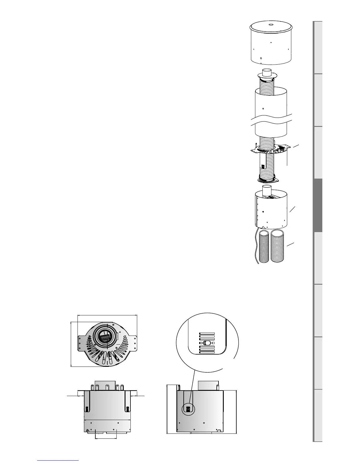
The Universal Vertical Powerflue (UVP) internal configuration is designed to
have the fan, mounted within the roof space of the house, and the vertical
Ø225mm diameter liner, containing a Ø100mm flexi, penetrate through
the roof. The UVP internal conversion kit comes with a 1200mm liner that is
specific to the internal installation and must always be used.
Note: The flue setup must comply with either section D1 on page 14 or D2 on
page 16.
Use standard methods to flash the roof penetration. The installation must be
weatherproof and conform to all local council standards including powered flue
termination rules.
Mount the fan mount bracket (1) to the roof framing and strapping using
timber ensuring that the flue is rigid and vertical. Ensure that the mounting
timber does not obstruct access to the 3xM5 screw threads on the side of the
fan unit.
Aim to have the fan enclosure (2) mounted as high as possible, mainly to allow
sucient fall for condensation drainage if the flexi-flue is to run horizontally.
Ensure there is sucient space below fan enclosure (2) to have access to fit the
flexi-flue tubes (3) and allow flowing bends if required.
Note: The UVP-Internal and the flexi flue connections must be installed in a
location accessible for service or replacement; a service hatch or removable flashing
to allow access may be required.
Note: When installing the unit onto a flue liner, ensure the length of flue liner above the roof is the minimum
required length. ENSURE the Ø25mm restriction plate is installed on the inlet.
Head and Sill scale 1:5
Jamb scale 1:5
framing member with
wall wrap and flashing
tape over
cladding on cavity
batten
typical head flashing with
stop ends to comply with
relevant building code
horizontal powerflue
unit
terminal fixing brackets
(shown dashed) fixed
to framing
flashing tape over wall
wrap to opening
seal air gap to opening
terminal screw fixed to flange
with flange fixed to studs at
fixing brackets
packer to lift terminal off
sill
sill cover to cladding to compl
with relevant building code
300 min
360 min
10
cladding on cavity
batten
10
horizontal powerflue
unit
terminal screw fixed to flange
with flange fixed to studs at
fixing brackets
terminal fixing
brackets screw fixed
into framing
framing member with
wall wrap and flashing
tape over
continuous sealant strip
to jambs
scriber or plug may be
required - dependent on
cladding type
seal air gap to opening
cowl
198
138 60
scale: date:
ecn:
drawn:
drawing no:
revision:file:
Horizontal Powerflue Detail
as shown ECN-2155 EDA-0006 MGD-Series FLUE Master File.dwg
V. 02 08.12.2017
 Loading...