6
A
Installation Process and Product Description
A1 Recommended Installation Process
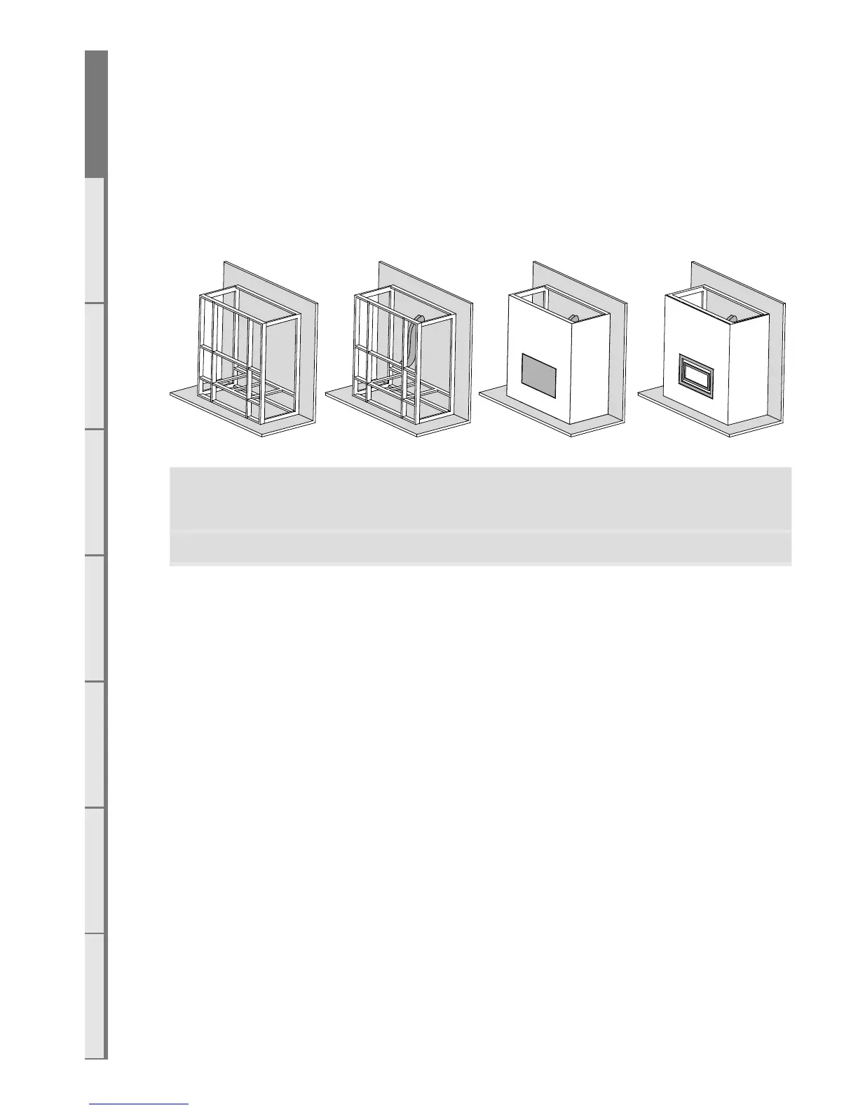
The following diagram illustrates the steps required to install your gas fire.
The sequence in which you choose to do these tasks will vary depending on your individual
scenario. Please read these instructions fully before proceeding with the installation. Leave the
installation of the fascia panels until the very end of the installation and commissioning to avoid
damage to the fascia panels.
Create the Cavity Install electrical / gas
connections and ue
system
Install appliance and
nish cavity
Finish installation,
t fascia and test
appliance
Section B Section C, D Section E Section F
A2 Product Description
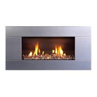
The Escea DL series gas fire is a room sealed gas appliance designed to be built into a cavity.
These appliances are flued using collinear flexible aluminium flue (with PolyPro flue extensions in
some installations) connected to a powerflue.
The user will control their fire with the Radio Frequency (RF) remote that will normally be left
in its wall mount cradle. In addition to the RF remote the appliance has a single auxiliary On/O
button on the unit. When not in operation it is in a standby mode unless it is physically isolated
from the mains supply.