26
If there is not enough room to reach into the cavity the appliance may need to be pulled forward
slightly out of the cavity. Stretch out the last 300mm of the flues, and reach through into
the cavity and connect both the inlet flue (Ø75mm) and the exhaust flue (Ø100mm) to their
respective spigots on the rear of the appliance. Orientate and position the hose band clamps to
provide easy access from the front of the appliance. Tighten the flue onto the spigots by the use
of the hose clamps (provided). Ensure the flue connection is as sound as possible and that the
flue connection is air tight.
E4 Fixing the Appliance to the Base and Wall
There are several ways that the appliance can be fixed against movement: It is a requirement
that this appliance be securely fastened to the wall and base.
NOTE: It is important that the outer fascia is used during this process to ensure that the appliance is
located in the appropriate position within the cavity.
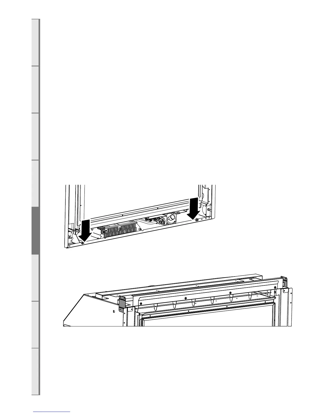
E5 Fixing Appliance to Base
The appliance has several holes along the front edge of the base panel that have been provided
to allow installers to screw the appliance to the floor. Because of a lack of access for drilling
it may be necessary to mark the appropriate location for these screws and then remove the
appliance and drill holes into hard flooring.
Alternatively a socket set can be used to drive in hex headed screws.
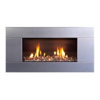
E6 Fixing Appliance to Wall
The installer must also fix the appliance to the sides of the cavity using the brackets on the side
of the appliance shown below. These flanges can be bent to accommodate the installation.