20
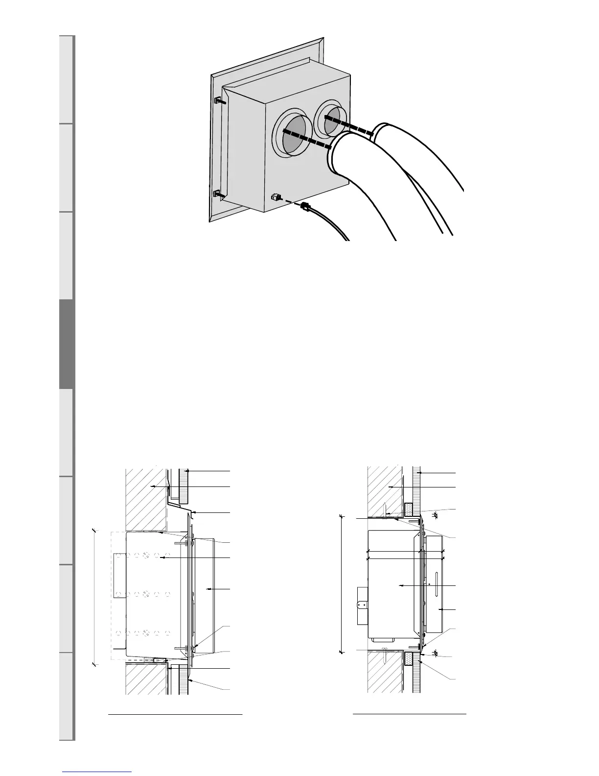
Fit the horizontal powerflue wall terminal into the hole and fix in place, making sure the
installation is sealed appropriately to prevent the ingress of water from outside the wall cladding.
NOTE: It is the responsibility of the installer to ensure the horizontal powerflue wall terminal is
installed to all relevant building codes to ensure weather tightness. This may necessitate the use of
appropriate flashing material where appropriate.
IMPORTANT: Ensure that flashings do not restrict the air intake slot around the periphery of
the cowl
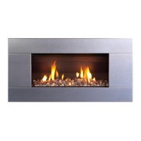
How to Flash the Horizontal Powerflue
The following diagrams are excerpts from the Escea architect drawings and are available in full on
our website. These diagrams are recommendations, and your installation must comply with any
local or national building codes.
Head and Sill scale 1:5
framing member with
wall wrap and flashing
tape over
cladding on cavity
batten
typical head flashing with
stop ends to comply with
relevant building code
horizontal powerflue
unit
terminal fixing brackets
(shown dashed) fixed
to framing
flashing tape over wall
wrap to opening
seal air gap to opening
terminal screw fixed to flange
with flange fixed to studs at
fixing brackets
packer to lift terminal off
sill
sill cover to cladding to comply
with relevant building code
300 min
360 min
10
cladding on cavity
batten
10
horizontal powerflue
unit
terminal screw fixed to flange
with flange fixed to studs at
fixing brackets
terminal fixing
brackets screw fixed
into framing
framing member with
wall wrap and flashing
tape over
continuous sealant strip
to jambs
scriber or plug may be
required - dependent on
cladding type
seal air gap to opening
cowl
198
138 60
scale: date:
ecn:
drawn:
drawing no:
revision:file:
Horizontal Powerflue Detail
as shown ECN-2155 EDA-0006 MGD-Series FLUE Master File.dwg
V. 02 08.12.2017
framing member with
wall wrap and flashing
tape over
cladding on cavity
batten
typical head flashing with
stop ends to comply with
relevant building code
horizontal powerflue
unit
terminal fixing brackets
(shown dashed) fixed
to framing
flashing tape over wall
wrap to opening
seal air gap to opening
terminal screw fixed to flange
with flange fixed to studs at
fixing brackets
packer to lift terminal off
sill
sill cover to cladding to compl
with relevant building code
300 min
360 min
10
cladding on cavity
batten
10
horizontal powerflue
unit
terminal screw fixed to flange
with flange fixed to studs at
fixing brackets
terminal fixing
brackets screw fixed
into framing
framing member with
wall wrap and flashing
tape over
continuous sealant strip
to jambs
scriber or plug may be
required - dependent on
cladding type
seal air gap to opening
cowl
198
138 60
scale: date:
ecn:
drawn:
drawing no:
revision:file:
Horizontal Powerflue Detail
as shown ECN-2155 EDA-0006 MGD-Series FLUE Master File.dwg
V. 02 08.12.2017