Fire Alarm Computer 8000C
Page 93
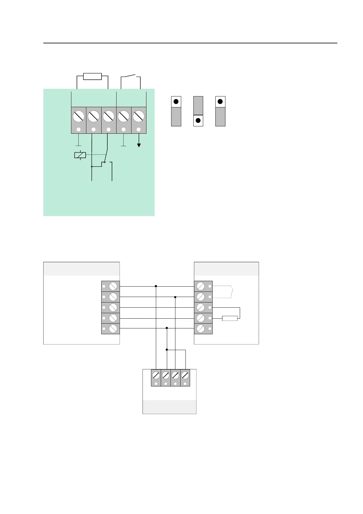
Operating mode: positiv switching (+12 V DC
intern
/ max. 1A) and monitored
680
R *
S*
GÖS
RÜCK.
GND
K1
+12V DC Ub int.
K1
+monitoring
panel int.
BR8 BR7 BR6
1
2
3
1
2
3
1
2
3
Fig. 48: Terminal of the master box relay K1
Master box
(schematic circuit diagram)
Fire alarm control panel 8000 C
Field device module
680
Ω
S*
R*
FSK adapter SDA-97
784708
10 9 8 7
+UB
+
-
ÜE -
ÜE +
+ UB ext.
alarm
+UB
S
G
acknowledge
MFAB acknowledge
Fig. 49: Schematic circuit diagram master box with FSK adapter
Field device module