73
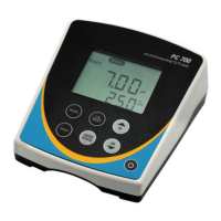
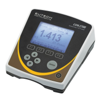
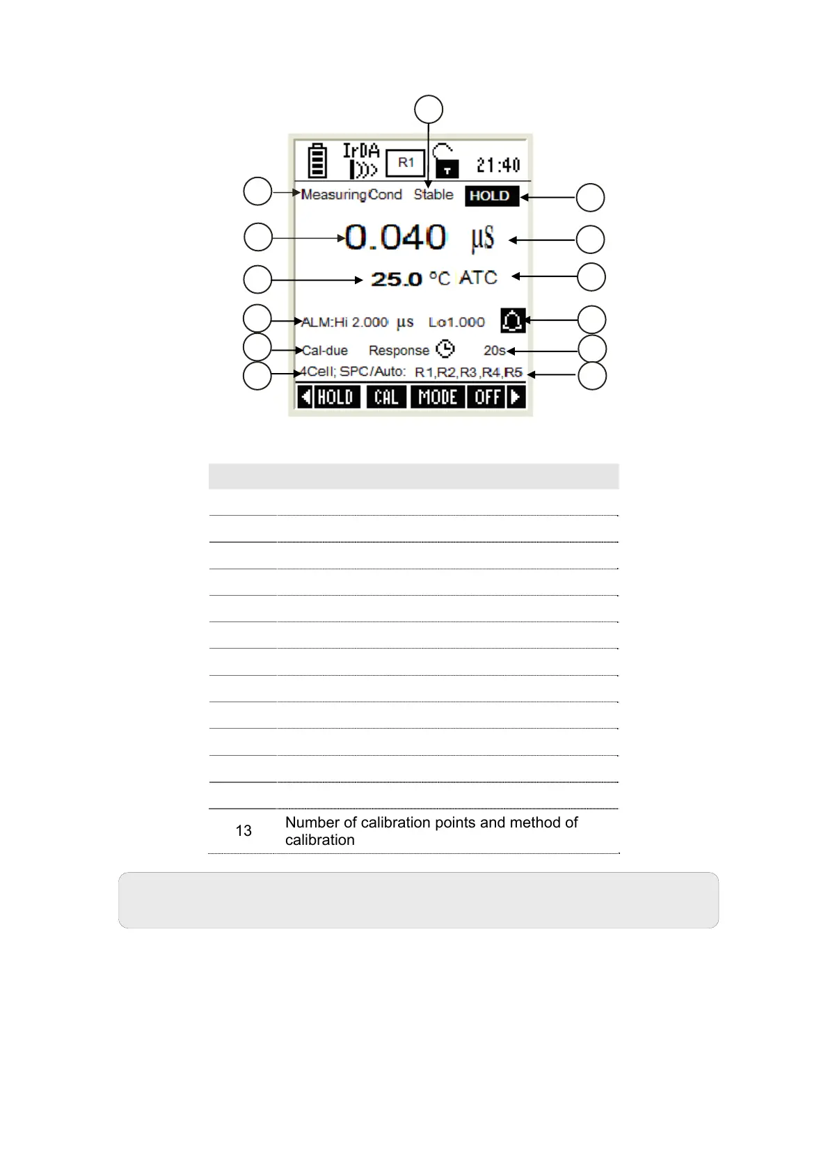
Figure 34 : Conductivity Measurement Screen
Item Description
1 Measurement mode indicator
2 Appears when the reading is stable
3 Appears when the reading is on hold
4 Conductivity reading
5 Units of measurement
6 Temperature reading & units
7 Temperature compensation mode
8 Conductivity HI & LO Alarm limits
9 Conductivity Alarm indicator
10 Calibration Due indicator
11 Response time of the CON probe
12 Conductivity ranges (that have been calibrated)
13
Number of calibration points and method of
calibration
Note: Lower display shows ‘2Cell’ or ‘4Cell’ when a 2-cell or 4-Cell
conductivity probe is connected.
1
4
6
8
10
11
3
5
7
9
12
2