Do you have a question about the evertz 5600MSC and is the answer not in the manual?
Explains the manual's organization and how to find information within it.
Provides definitions for technical terms used in the manual, such as 4:2:2 and 4Fsc.
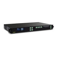
Describes the purpose and function of each connector on the rear panel of the 5600MSC.
Details the physical rack mounting specifications and procedures for the 5600MSC unit.
Explains how to connect general purpose inputs and outputs via the AUX I/O connector.
Describes how to connect serial ports for synchronized operation between 5600MSC units.
Covers mounting the GPS antenna, connecting it to the 5600MSC, and system startup.
Provides an overview of the 5600MSC front panel keys, display, LEDs, and shaft encoder.
Details the data displayed on the alphanumeric display and special front panel indicators.
Explains the various status messages for GPS, time, frequency references, modem, and system status.
Guides users on configuring frequency, time, VITC, and genlock references for the 5600MSC.
Details the extensive configuration options for LTC, Sync, Analog, SDI, HD SDI, Audio, DARS, and AES outputs.
Covers selection of power, rate, synchronization, offset, time zone, DST, parity, color frame, and level for LTC outputs.
Details clock frequency, standards, VITC generation, and phase settings for video sync outputs.
Covers standard selection, phase, on-screen message display, and moving line for analog video test generator.
Details standard, phase, on-screen message display, embedded audio, and moving line for SDI test generator.
Covers standard, genlock, phase, on-screen message display, embedded audio, color space, and captioning for HD SDI test generator.
Allows setting millisecond, microsecond, and nanosecond phase offsets for multiple outputs.
Details configuration of audio level, start time, sound type, frequency, duration, testing, and sequences for analog audio.
Covers phase settings, channel frequency, audio level, and lock type for DARS and AES outputs.
Covers serial port mode, modem setup, firmware, operation modes, presets, IP, NTP, and system time/date settings.
Sets the mode of operation for the COM serial port for firmware upgrades or synchro modes.
Configures which test generators are excluded from synchronization operations.
Details modem operating mode, standard, speaker volume, phone number, dial time, and retries.
Sets the function of the two general purpose outputs (GPO 1 and GPO 2).
Sets the function of the two general purpose inputs (GPI 1 and GPI 2).
Explains DST transition logic and how to set entry mode, start/end times, and offset.
Covers viewing firmware versions and upgrading firmware for the 5600MSC and HD Test Generator.
Allows switching between Engineering and User operation modes for the 5600MSC.
Enables saving and recalling user-defined configurations and factory presets.
Details setting the IP address, mode, subnet mask, gateway, and gateway enable status.
Covers setting up NTP restrictions by defining IP addresses and masks to ignore.
Allows setting the system time when no external time reference is available.
Allows setting the system date when no external time reference is available.
Covers setting manual user bits and selecting user bit modes for time code output.
Describes how the 5600MSC operates when locked to GPS satellites for frequency and time.
Lists detailed technical specifications for sync outputs, 10MHz I/O, LTC, Genlock, comms, GPS, test generators, electrical, and physical attributes.
Provides step-by-step instructions for upgrading the 5600MSC and HD Test Generator firmware.
Outlines essential servicing instructions, including fuse replacement, for qualified personnel.
Explains how to connect to and use VistaLINK® for configuring menus in User Mode.
| Brand | evertz |
|---|---|
| Model | 5600MSC |
| Category | Portable Generator |
| Language | English |