Model 5600MSC Master Clock/SPG Manual
INSTALLATION
Revision 1.6 Page 2-1
2. INSTALLATION
2.1. REAR PANEL
AUX I/O
GPSCOM
FUSE:
1.0 A
MODEL
5600MSC
ETHERNET
LN ACT 10/100
MODEM
123 456
IN
LTC OUT
OUT
10MHz
DARS / A ES / ANA LOG
ANALOG TG OUT AES OUT
BANK 1 SYNC OUT BANK 2 SYNC OUT
SDI BLACK
2
1
2121
TG GENLOCK
MICROSYSTEMS LTD.
MADE IN CANA DA
SDI TG OUT
2
1
SD
DARS OUT
SD
SDI TG OUT
HD
SDI BLACK
HD
D
ALR
GENLOCK
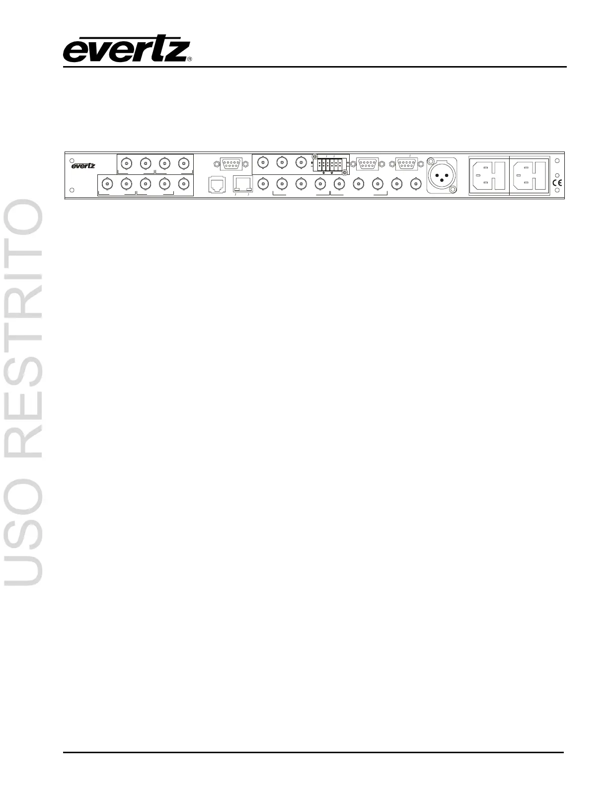
Figure 2-1: 5600MSC Rear Panel
The following sections describe the purpose of the rear panel connectors of the 5600MSC. Sections
2.1.1 to 2.1.6 describe the specific signals that should be connected to the 5600MSC.
2.1.1. 10 MHz Connections
10 MHz IN: This BNC connector is for input for 5 or 10 MHz reference. When power is off, this
output will be a direct relay connection to the 10 MHz OUT. The FREQUENCY REF
menu item must be set to 10 MHz freq ref in order to lock the 5600MSC master oscillator
to the 10 MHz input.
10 MHz OUT: This BNC connector is for the 10 MHz output signal generated by the 5600MC. When
power is off, this output will be a direct relay connection to the 10 MHz IN. When the
GPS option (G Option) is installed, this output can be referenced to the GPS frequency
reference providing superior long term stability.
2.1.2. Reference Video Connections
GENLOCK: This BNC connector is for connecting an NTSC or PAL colour black signal to be used as
the frequency reference for the 5600MSC. The FREQUENCY REF menu item must be
set to Video freq ref in order to lock the 5600MSC master oscillator to the genlock input.
The GL RANGE menu item is used to set the frequency tolerance used when genlocking
to the video reference. See section 3.5.1 and 3.5.4. The input is high impedance and
must be properly terminated with 75 ohms using an external termination.
2.1.3. Sync Outputs
SYNC 1 to 6: These BNC connectors provide two banks of 3 sync pulse / colour black outputs that can
be independently timed. The BANK1 SETUP and BANK 2 SETUP menu items on the
OUTPUT Setup menu are used to set the types of outputs available on each bank of
connectors. The SYNC 1 OUTPUT to SYNC 6 OUTPUT group of sub-menus on the
OUTPUT Setup menu are used to configure these outputs and set up their timing. See
section 3.6.2.
2.1.4. Ethernet Connections
The 5600MSC menu system can be configured using the VistaLINK
TM
-C Configuration tool connected
by Ethernet. (See section See section 3.7.10 in the GENERAL menu descriptions for information on
configuring the IP address of the 5600MSC and section 4.4 for information about installing and using
the VistaLINK
TM
software) When the 5600MSC is fitted with the NTP option (T option) it can also be