Model 5600MSC Master Clock/SPG Manual
Page 2-2
Revision 1.6 INSTALLATION
used as an Network Time Protocol server connected to other devices by Ethernet. (See section 0 in
the GENERAL menu descriptions for information on configuring the NTP functions of the 5600MSC.)
The 5600MSC is designed to be used with either 10Base-T (10 Mbps) or 100Base-TX (100 Mbps) also
known as Fast Ethernet, twisted pair Ethernet cabling systems. When connecting for 10Base-T
systems, category 3, 4, or 5 UTP cable as well as EIA/TIA – 568 100Ω STP cable may be used. When
connecting for 100Base-TX systems, category 5 UTP cable is required. The cable must be “straight
through” with a RJ-45 connector at each end. Make the network connection by plugging one end of the
cable into the RJ-45 receptacle of the 5600MSC and the other end into a port of the supporting hub.
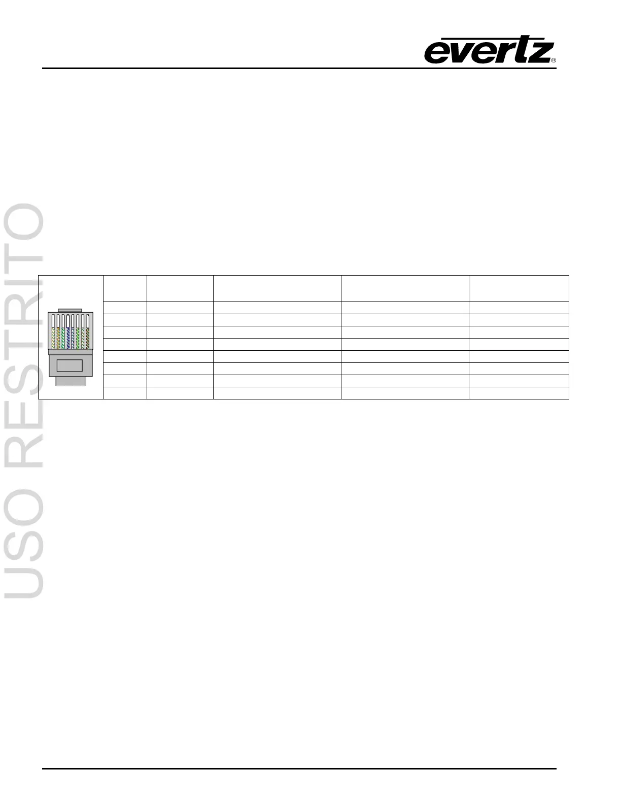
The straight-through RJ-45 cable can be purchased or can be constructed using the pinout information
in Table 2-1. A colour code wiring table is provided in Table 2-1 for the current RJ 45 standards (AT&T
258A or EIA/TIA 258B colour coding shown). Also refer to the notes following the table for additional
wiring guide information.
Pin # Signal EIA/TIA 568A AT&T 258A or
EIA/TIA 568B
10BaseT
or 100BaseT
1 Transmit + White/Green White/Orange X
2 Transmit – Green/White or White Orange/White or Orange X
3 Receive + White/Orange White/Green X
4 N/A Blue/White or Blue Blue/White or Blue Not used (required)
5 N/A White/Blue White/Blue Not used (required)
6 Receive – Orange/White or Orange Green/White or Green X
7 N/A White/Brown White/Brown Not used (required)
Pin
1
8 N/A Brown/White or Brown Brown/White or Brown Not used (required)
Table 2-1. Standard RJ45 Wiring Colour Codes
Note the following cabling information for this wiring guide:
• Only two pairs of wires are used in the 8-pin RJ 45 connector to carry Ethernet signals.
• Even though pins 4, 5, 7 and 8 are not used, it is mandatory that they be present in the cable.
• 10BaseT and 100BaseT use the same pins, a crossover cable made for one will also work with the
other.
• Pairs may be solid colours and not have a stripe.
• Category 5 cable must use Category 5 rated connectors.
The maximum cable run between the 5600MSC and the supporting hub is 300 ft (90 m). The maximum
combined cable run between any two end points (i.e. 5600MSC and PC/laptop via network hub) is 675
feet (205 m).
Devices on the ethernet network continually monitor the receive data path for activity as a means of
checking that the link is working correctly. When the network is idle, the devices also send a link test
signal to one another to verify link integrity. The 5600MSC rear panel is fitted with two LEDs to monitor
the Ethernet connection.
10/100 This Amber LED is ON when a 100Base-TX link is last detected. The LED is OFF when
a 10Base-T link is last detected (the LINK LED is ON). Upon power-up the LED is OFF
as the last detected rate is not known and therefore defaults to the 10Base-T state until
rate detection is completed.
LN/ACT This dual purpose Green LED indicates that the 5600MSC has established a valid
linkage to its hub, and whether the 5600MSC is sending or receiving data. This LED will