Model 5600MSC Master Clock/SPG Manual
xii
Revision 1.6
Figures
Figure 1-1: Redundant Master Clock/SPG with Auto Changeover System Diagram....................................1-2
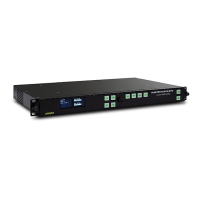
Figure 2-1: 5600MSC Rear Panel..................................................................................................................2-1
Figure 2-2: Typical GPIO Circuitry. ................................................................................................................2-7
Figure 2-3: Pole Mounting the Smart Antenna...............................................................................................2-9
Figure 2-4: Accutime 2000 Smart Antenna to 5600MSC Interface Cable (Evertz part WA-T09)............... 2-10
Figure 2-5: Accutime 2000 Extender Cable ................................................................................................ 2-10
Figure 3-1: Model 5600MSC Front Panel Layout ..........................................................................................3-1
Figure 3-2: Sync Generation - GPS Frequency Reference ........................................................................ 3-10
Figure 3-3: Sync Generation – NTSC or 59.95 Hz Video Reference ......................................................... 3-10
Figure 3-4: Sync Generation – PAL or 50 Hz Video Reference.................................................................. 3-10
Figure 3-5: Sync Generation – 10 MHz Reference – NTSC outputs .......................................................... 3-11
Figure 3-6: Sync Generation – 10 MHz Reference – PAL outputs ............................................................. 3-11
Figure 3-7: Sync Generation – No Reference – NTSC outputs.................................................................. 3-11
Figure 3-8: Sync Generation – No Reference – PAL outputs..................................................................... 3-12
Figure 3-9: Video Sync Phase Alignment in 59.94 Hz Field Rate Systems................................................ 3-28
Figure 3-10: Video Sync Phase Alignment in 50 Hz Field Rate Systems................................................... 3-29
Figure 4-1: VistaLINK
®
Configuration – Input Menu Pruning...................................................................... 4-10
Figure 4-2: VistaLINK
®
Configuration – Output Menu Pruning ................................................................... 4-11
Figure 4-3: VistaLINK
®
Configuration – General Menu Pruning ................................................................. 4-12
Tables
Table 2-1. Standard RJ45 Wiring Colour Codes............................................................................................2-2
Table 2-2: LTC OUT Pin Definitions...............................................................................................................2-3
Table 2-3: COM Port Pin Definitions..............................................................................................................2-3
Table 2-4: GPS Serial Port Pin Definitions.....................................................................................................2-4
Table 2-5: AUX I/O Pin Definitions.................................................................................................................2-4
Table 2-6: DARS/AES/ANALOG Terminal Strip Pin Definitions ....................................................................2-5
Table 2-7: 5600MSC-1-0-30 Synchro Cable..................................................................................................2-8
Table 3-1: Top Level of the Input Setup Menu...............................................................................................3-9
Table 3-2: Top Level of the Output Setup Menu......................................................................................... 3-17
Table 3-3: 525 Line Test Signal Selection .................................................................................................. 3-33
Table 3-4: 625 Line Test Signal Selection .................................................................................................. 3-33
Table 3-5: Valid Genlock Types.................................................................................................................. 3-40
Table 3-6: HD SDI Test Signal Selection.................................................................................................... 3-46
Table 3-7: Top Level of the General Setup Menu....................................................................................... 3-54