EMR User's Guide
High Density Modular Audio Router (AES, Analog, MADI, TimeCode, Data)
COMPONENT OVERVIEW Revision 1.8 Page 65
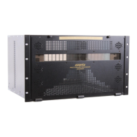
2.2.11. EMR-PR48-A Data Module
The EMR-PR48-A is a data port router card for the EMR. Each of the 48 data ports available on the
module can be configured to support either RS-442 or RS-232 serial protocols.
Each port consists of 2 reconfigurable transceivers allowing the port router to transmit or receive on each
of the Tx/Rx (sub port) connections. When the port is set at as Controller, sub port A (pins 34/18 for port 1)
is configured as a transmitter and sub port B (pins 2/19 for port 1) as a receiver, setting the port as a Slave
reverses the directions.
The EMR-PR48-A rear panel occupies 2 slots in a frame and uses 50-pin D-Sub female connectors as
shown in Figure
2-37. Each connector supports 8 serial data ports (RS-232 or RS-422). The pin out for
each connector is shown in Table
2-23.
Before installing the EMR-PR48-A, some consideration should be given to the cabling to ensure that
different VTR’s and RS-422 devices will be supported correctly. Figure
2-37 shows the first 8 ports
allocated in a typical application.
In this example, all the EMR-PR48-A ports are wired in exactly the same way. Any Tx/Rx swaps that are
required to support controlling (edit controller) or slave (VTR) devices is defined by the VL-Pro
configuration.
Notes about serial wiring to the EMR-PR48-A:
1. The use of DB9 patch panels is optional but it is recommended that you use a consistent signal
connection scheme to allow any pair of devices to be patched together.
2. RS-422 connections should be made using screened dual twisted pair cabling. Short runs of ribbon
cabling (<3m) can be supported, longer runs may affect the advanced features of the card.
3. A GND reference connection must be provided in the cable between the EMR-PR48-A and the
remote device.
4. If the external device supports the Sony pin 5 modes then the device’s Sony pin must be wired to
the EMR-PR48-A.
2.2.11.1. Learn Modes
The EMR-PR48-A has features to aid the user in establishing serial link connectivity quickly.
Learn Activity Mode: This can be used with the port standard set to RS-232 or RS-422. In this mode the
EMR-PR48-A listens for activity on both of the sub ports in order to find out which sub port is receiving
data. The user will need to cause the connected device to send data in order for this mode to function.
Single or Multiple ports may be learned at the same time.
Learn Driver Mode: This mode is only supported with standard set to RS-422. In this mode the EMR-
PR48-A interrogates the 2 sub ports to find out which one is connected to the external driver. No data
activity is required on the links but the external driver must be active. It is important that the receiver port
connections are not reversed so if the ports polarity is incorrect then a warning message is shown.
Depending upon the amount of data present on the link, the mode may fail to detect properly. It is usually
sufficient to just repeat the learn request.
 Loading...