52 05 2013 4365 00
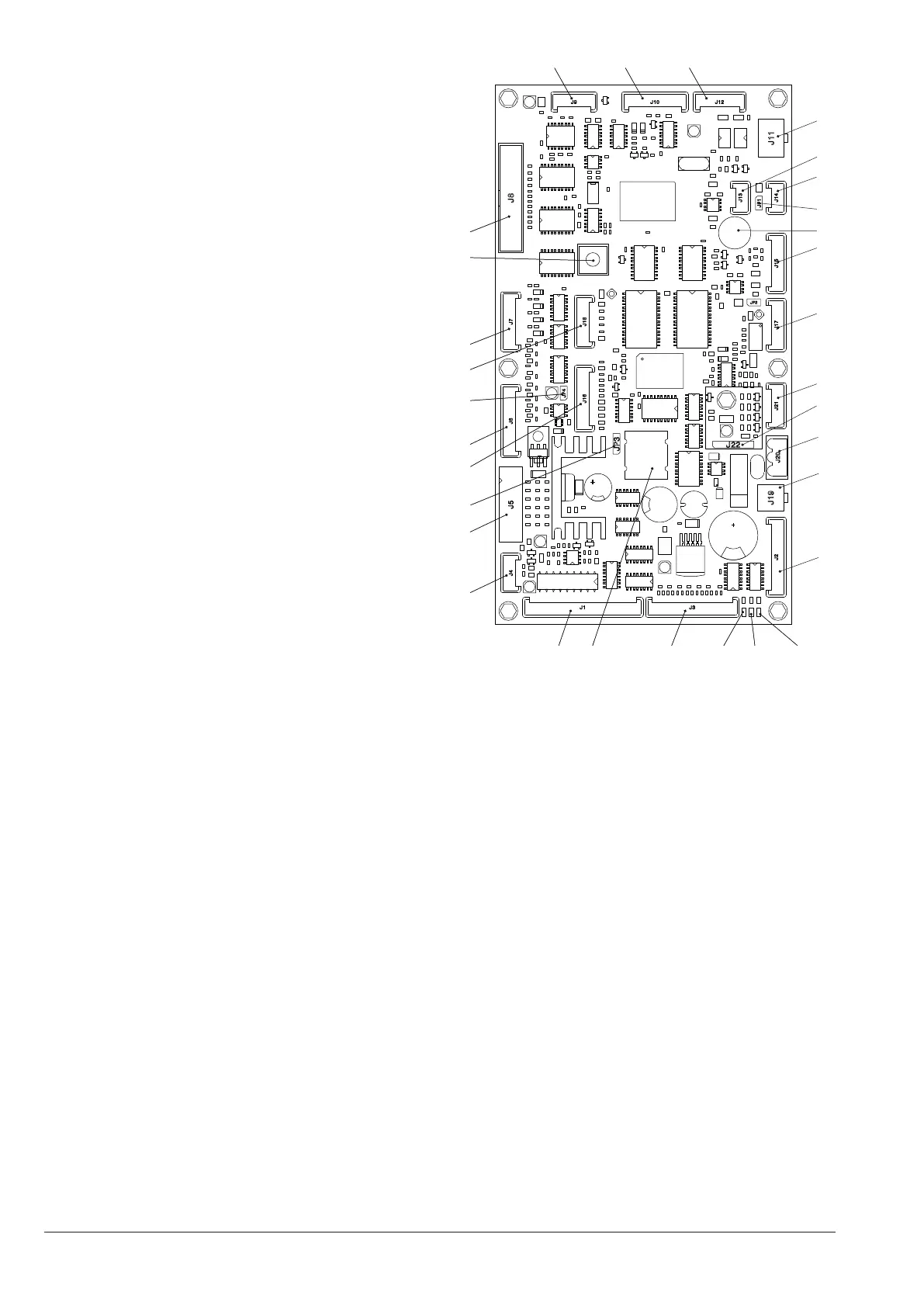
CPU BOARD
The CPU board (Central Process Unit) manages all
intended users for maximum conguration and manages
the incoming signals from a keyboard, payment system
and manages the activations card.
The LEDs, during the operation, give the following indi-
cations:
- the green LED (26) flashes during the normal operation
of the CPU board;
- the yellow LED (28) is on in the presence of 5 Vdc;
- the red LED (27) is on when there is, for any reason, a
reset of the software.
softWare update
The machine is equipped with Flash EPROM which can
be rewritten.
By means of an appropriate programme and a suitable
system (PC or PDA) it is possible to rewrite the man-
agement software of the machine without replacing the
EPROMs.
1
2
3
4
5
6
7
8
9
10
14
15
16
17
18
19
20
21
22
23
24
25
26
27
28293031
Fig. 39
1- (J4) Micro door (optional)
2- (J5) Validators
3- Battery bridge (2-3)
4- (J16) To the buttons/LED board
5- (J6) Not used
6- Jumper JP4 WDI (Closed)
7- (J18) Up-key
8- (J7) Numeric selection keyboard (optional)
9- Programming input button
10- (J8) Display
11- (J9) Numeric selection keyboard
12- (J10) RS232 Serial
13- (J12) EXE/BDV Payments
14- (J11) MDB Payments
15- (J13) Can-Bus
16- (J14) Can-Bus
17- Jumper Can-Bus JP1 (Closed)
18- Buzzer
19- (J15) Not used
20- (J17) Not used
21- (J21) Not used
22- (J22) RAM data expansion (optional)
23- (J20) Power supply 34Vdc
24- (J19) Door lighting connection
25- (J2) Stroke counter
26- DL3 “RUN” green LED
27- DL2 “RESET” red LED
28- DL1 “+5V” Yellow LED
29- (J3) Service buttons, tag lighting
30- Battery
31- (J1) Not used