53 05 2013 4365 00
ACTIVATION BOARD
This board activates, through relays, the equipment
working and the DC motors directly. It manages the sig-
nals originating from the cams and/or microswitches on
the various equipment. Furthermore, it controls the boiler
management board. The board works with 24 Vac for the
electronic parts and the payment systems.
The board management software is loaded directly,
(through RS232) on the microprocessor.
- The green LED 3 flashes during the normal operation
of the board;
- The yellow LED 6 indicates the presence of 5 Vdc.
- The red LED 4 is on during the board reset
- The red LED 2 (not used on this model), indicates the
operating status of the instant drinks boiler resistance.
- The red LED 5 indicates the operating status of the
instant boiler resistance.
- The green LED 8 (not used on this model) indicates the
pulses of the volumetric counter.
- The green LED 5 indicates the presence of 34Vdc.
- The green LED 7 indicates the presence of regulated
34Vdc.
relay funCtion (see the Wiring diagram)
RELAY USER
RL1 = Not used
RL2 = Not used
RL3 = Not used
RL4 = Not used
RL5 = Not used
RL6 = Not used
RL7 = EEA
RL8 = Not used
RL9 = MSB
RL10 = MSCB
1
2
3
4
5
6
7
8
9
10
11
12
13
14
15
16
17
18
19
20
21
22
23
24
25
26
27
28
29
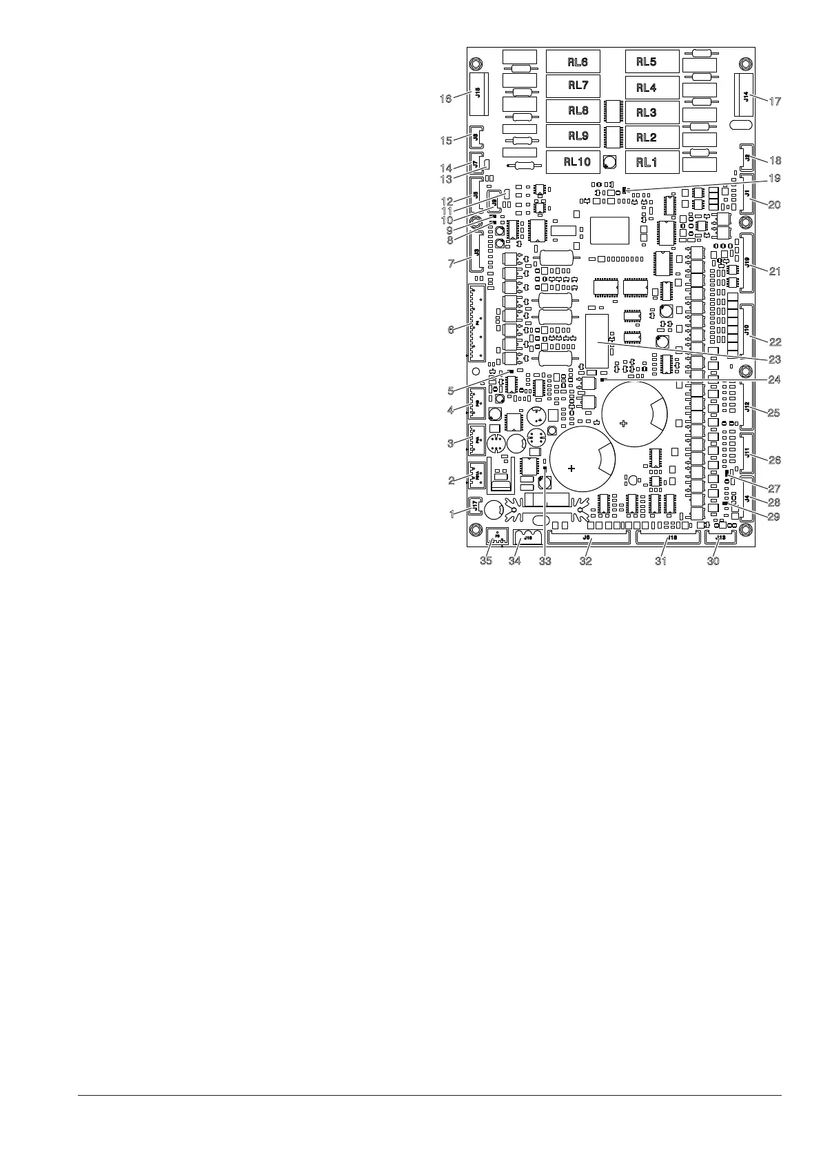
Fig. 40
1- (J17) Powder extraction
2- (P21A) 34Vdc safety relay coil and door input
3- (P4A) CPU Power supply
4- (P4B) CPU Power supply
5- Led
6- (P4) Piston motor and infuser unit brush motor
7- (J3) Not used
8- Led 2
9- Led 1
10- (J9) Not used
11- Not used
12- (J5) Probe and boiler relay
13- CAN BUS jumper
14- (J7) CAN-BUS
15- (J8) CAN-BUS
16- (J15) Users
17- (J14) Not used
18- (J2) Not used
19- Led 4
20- (J1) Not used
21- (J19) input / output 24V
22- (J10) Motor-dispensers
23- 34Vdc Safety Relay
24- Led 7
25- (J12) Mixer motors
26- (J11) Pump
27- Led 3
28- (J4) RS232 Connector
29- Led 8
30- (J13) Not used
31- (J18) Input
32- (J6) Input
33- Led 6
34- (J16) 24 Vac Power supply
35- (P8) Not used