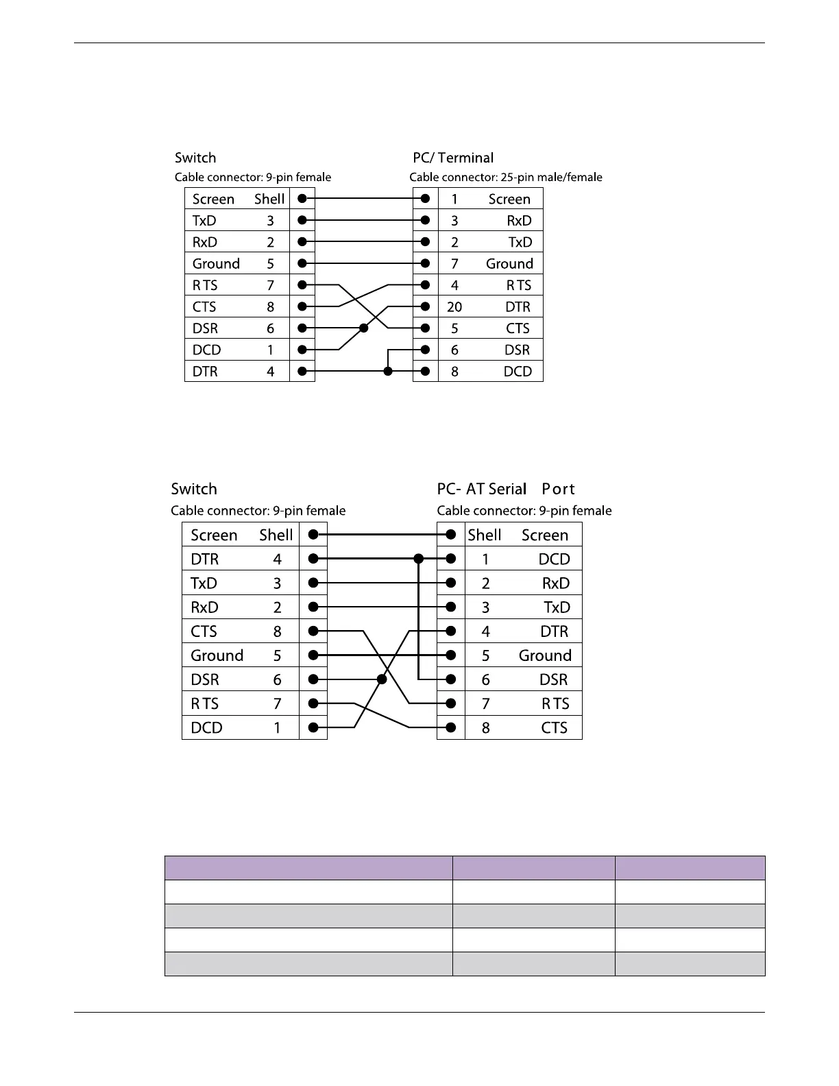
Figure 321 shows the pinouts for a 9-pin to 25-pin (RS-232) null-modem cable.
Figure 321: Null-Modem Cable Pinouts
Figure 322 shows the pinouts for a 9-pin to 9-pin (PC-AT) null-modem serial cable.
Figure 322: PC-AT Serial Null-modem Cable Pinouts
Table 358 shows the pinouts for the RJ45 console port on the ExtremeSwitching switches.
Table 358: RJ45 Console Port on Switch
Function Pin Number Direction
CTS (clear to send) 1 In
DTR (data carrier detect) 2 Out
TXD (transmit data) 3 Out
GND (ground) 4 —
Console Connector Pinouts Technical Specifications
476 ExtremeSwitching Hardware Installation Guide
 Loading...

