Chapter 7: Installing Summit External Power Supplies
Summit Family Switches Hardware Installation Guide
328
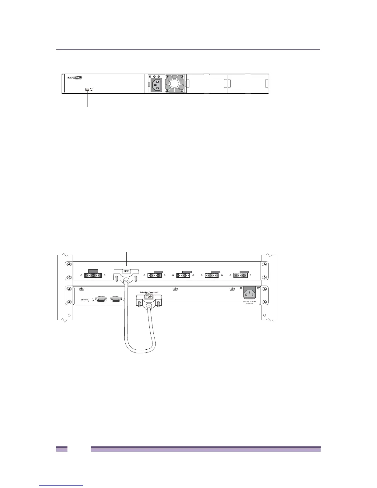
Figure 271: EPS-C2 Connector Selector Switch
After the EPS-C2 has been installed in a rack and the power supplies have been installed, do the
following to connect the redundant power cables:
1 Set the connector selection switch for either the 2X9 or 2X7 connectors.
2 Connect the keyed end (for the 2x7 connector cable, the end with the tab offset from the edge of the
connector pins) of the redundant power cord to the EPS-C2 chassis (see Figure 272). Verify that the
side of the connector marked TOP is facing up.
3 Connect the other end of the redundant power cable (for the 2x7 connector cable, the end with the
key flush with the edge of the connector pins) to the Summit switch (see Figure 272). Be sure that the
side of the connector marked TOP is facing up.
Figure 272: Installing the Redundant Power Cord
4 Repeat steps 2 and 3 to connect any additional redundant power cords.
Connecting the AC Power cord to the EPS-C2
After the redundant power cord is connected between the EPS-C2 and the switch, and an AC power
cord to the internal power supply of the switch is attached to a power source (see Chapter 6, “Installing
Summit Family Switches.”), install the AC power cord to the power supplies in the EPS-C2 as follows:
ESP-C2_01a
Connector selector switch
2x9 Output
2x7 Output
Power Configuration Selector
EPS-C2
ESP-C2_02
! See M anual
Redundant Power putOut
! See M anual
Redundant Power putOut
! See M anual
Redundant Power putOut
! See M anual
Redundant Power putOut
! See M anual
Redundant Power putOut
! See M anual
Redundant Power Output
Connect First
! See Manual
! See Manual
 Loading...