MLC 62 Series • Hardware Setup
2-13
3. On the back of the faceplate, place the new
pair of buttons through the two slots in
which they will be installed. Line up the
two pegs in the upper-left and lower-right
corners of the new button membrane (see the
illustration at right) with the holes located at
opposite corners of the empty pair of slots in
the faceplate.
4. Press the two buttons into the faceplate until the pegs on
the membrane are seated in the corresponding holes.
5. Repeat steps 2 through 4 for any additional buttons that
you want to replace, then reattach the faceplate.
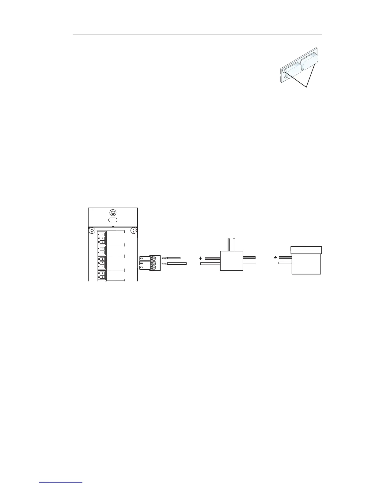
Wiring the Relays port
Connect one or two devices such as room lights, projector lifts, or
a motorized screen (shown in the example below) to the Relays
port. This port accommodates two relay connections.
Ground ( )
Ground ( )
Signal 110/220V
Rx
Connecting a motorized screen to the Relay port of
an MLC 62 RS D
In the example above, a low-voltage controller, connected to a
motorized screen, has been wired to pins 2 and 3 of the provided
3-pin captive screw connector. Plugging this connector into
the MLC's Relays port will connect the device to the MLC's
relay port 2 (pins 2 and Common of the MLC's 3-pole Relays
connector).
To connect devices to both relay ports:
1. Connect the ground wires of both devices to pin 3 of the
provided 3-pin connector.
2. Connect the signal wire of one device to pin 2 and the other
to pin 1 of the 3-pin connector.
MUTE
LAPTOP
Pegs (2)