MLC 62 Series • Hardware Setup
Hardware Setup, cont’d
2-6
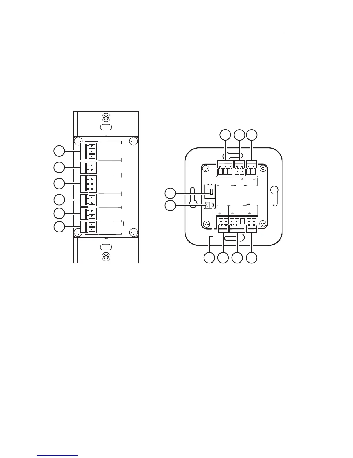
Rear panels
On both MLC 62 models, all rear panel connections are on
captive screw connectors. See the wiring and installation
sections later in this chapter for connection information.
(The illustrations below show MLC 62 RS models. The MLC 62
IR model, available as a future release, does not have the Digital
Input, Relays, or RS-232 [Serial] ports.)
Rx
Tx
GROUND
Tx/IR
COMMON
1
1
2
HOST/
CONFIG
RS-232
IR/ S
DIGITAL
INPUT
Tx
PWR
12 V
0.4 A MAX
RELAYS
N/O
GROUND
GROUND
GROUND
GROUND
+12 VDC
1
2
3
4
5
6
RS-232
IR/ S
RELAYS
N/O
PWR
12 V
0.4 A max
HOST/
CONFIG
DIGITAL
INPUT
+
Tx
Rx
1
Tx
Tx/
IR
1
2
C
1
2
3
4
5
6
9
1 2
8
R
7
a
Host/Config port — (Located on the front panel of the
MLC 62 D and on the right side panel of the MLC 62 EU). This
bidirectional serial port can be used for configuration and
firmware updates in the same way as the USB port (
f
in the
"Front and right side panels" section, earlier in this chapter).
The baud rate is 9600 bps. This port can be used as a backup for
the USB Configuration port.
b
Digital Input port — This port provides an additional way to
trigger functions on the MLC 62. Connect a switch to this 2-pole
connector to initiate commands via the MLC to the display or
other devices such as room lights or a motorized screen.